Showing posts with label Annotations. Show all posts

Monday, April 20, 2009

Revit 2010: New Coordinates Icons

The new coordinate systems and icons have a lot of even the best users confused. Go to a floor plan view and hit the light bulb to reveal the two new coordinate system icons (the survey point triangle and the project base point circle). Now... you can draw a simple building and link in a simple building (by shared coordinates) and move these two icons around a bit (clipped and unclipped) to see how the two models react or.. here is the simplest way I can put it:

1. There are now 3 coordinate systems in Revit... the revit internal coordinates, the shared coordinates, and the new the project coordinates. There is no icon for locating the revit internal coordinates but there are two new icons for the other coordinate systems... the survey point, and the project base point.


2. Clipped or unclipped the Project Base point is always the origin of the new project coordinates system.

3. Clipping the Project Base Point... pins the project base point icon to the revit internal coordinate system so you can drag around the revit internal system (which the host model is always attached to).

4. Unclipping the Project Base Point icon from the revit internal coordinates system... allows you to move the project coordinates system separately from the revit internal coordinates system.

5. Clipping the Survey Point... pins the survey point icon to the shared coordinates system so you can drag around the shared coordinates system (which only linked models might be attached to).

6. Unclipping the Survey Point icon from the shared coordinates system allows you to move it freely without moving the shared coordinates system.

7. The Survey Point icon was created for the export to Civil workflow.

8. Both icons report their location relative to the shared coordinates origin at all times and you can rotate true north from the project base point icon.

If you are still confused go back to my original suggestion... draw a simple building and link in a simple building (by shared coordinates) and move these two icons around a bit (clipped and unclipped) to see how the two models react. Trial and error is probably the best way to learn these new tools.

Thursday, April 16, 2009

Revit 2010: New Spot Slopes

Go to Annotate... Spot Slope... and you might notice that Revit has a new slope annotation that works in plan and elevation view. Now try annotating a roof slope with a spot annotation triangle and you might notice something peculiar. Maybe your roof is 6:12 but the annotation read 4:12. Why the error? Because Revit is annotating the Hip not the face of the roof...


Try hiting the tab key while floating over the roof edge and you'll see that the slope tag can report the slope of the hip or the face. The tool just happens to default to reporting the hip first.

This tool does not yet work on ramps or railings.

Tuesday, November 11, 2008

Using Radar

What is Radar?
Radar is a method of detecting distant objects and determining their position.

When do I need it?
You just linked a developed Revit model into a new project file and you can't seem to find it. Ever happen to you? I know it happens to many. This is where having radar comes in handy.

If I just imported a project and I can't seem to locate the imported model the first thing I do is setup my radar.
1. Go to a floor plan view and add four new elevations looking in all directions.
2. Highlight these new elevations in your project browser and go to element properties.
3. Uncheck Crop View and Far Clip Active parameters.
4. Open each view individually and zoom all (ZA) until you find the model you are looking for.

Users new to file linking can waste valuable time searching for imported models. Next time just tell them to setup their radar.

Saturday, January 13, 2007

Spot Dimensions Features

There's more to Spot Dimensions than meets the eye.

Within the Spot Dimension tool you can choose between spot elevations and spot coordinates. Spot Elevations will report the elevation of certain objects. Spot Coordinates will report the distance and direction of a point from an origin that you define (see Tools, Shared Coordinates... Specify Coordinates at a point)

While Spot Coordinates will report the coordinates of any model or drafting element it is not really clear in the help files that Spot Elevations will report the elevation of only certain parts of model elements. Here is the list of elevations that Spot Elevations will tag:

  • toposurfaces
  • roof eaves and ridges
  • stair steps and landings
  • window sills and door thresholds
  • tops of footings & beams
  • the sill and head of openings in a wall
  • any point within the area of (non-sloping) floors and ceilings
  • the height of a family's model objects (provided they are visible in the view)
  • apparently ramps too but I haven't figured this one yet
  • if you know of any more please add a comment
The visibility of Spot Elevations and Spot Coordinates can be controlled by the visibility of its host object or the visibility of the annotations themselves.

Taging the elevation of a horizontal surface won't work in wireframe mode. Spot Elevations may be deleted when trying to modify some objects in certain ways.

Two interesting parameters in the properties dialog are Relative Base and Elevation Origin. If you go to the type properties and change the Elevation Origin to Relative you will notice that the Relative Base instance parameter is no longer greyed out. You can now report the elevation of a point relative to any level you've created.

One nice thing about all Spot Dimensions is that you can control the units format separately from the project's units format by going to the type properties dialog so that their units display in decimal feet if you wish. It would be nice if levels had the same ability.

Friday, September 29, 2006

2D vs 3D Datum

You might notice that when you move the endpoint of a gridline in plan A it moves in plan B as well. Same goes for Reference Planes and Levels. Select a datum and it is selected in all views in which it is visible. You'll notice a blue icon that reads 3D. Click once on the icon and it switches to 2D mode. The datum is now view specific and free to move in this view independent from the same datum in other similar views.
Applying a crop region or scope box to a view can also affect the location of your datum extents.

To set a datum to 2D mode in all views select the datum, change it's mode to 2D and click on the Propagate Extents button in the options bar. The datum choosen is now free to move independently in all similar views.

Wednesday, August 02, 2006

Auto Dimension Options

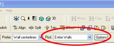
Select the Dimension tool. In the options bar "Pick: Entire Walls" and select the "Options" button.
Select an exterior wall and you'll notice that you can now dimension the windows, doors, grids, and intersecting walls along the entire length of a wall.

Tuesday, June 20, 2006

Section Annotation Features

There's more to Sections than meets the eye.

1. Goto the View... Section. You'll notice that you can select between a Building Section, Wall Section, and Detail View. Select the Detail View. In the options bar you'll notice that you can "Reference other view" (for referencing a drafting view that is already present). Place a Detail Section. Now goto View... Callout and place a Detail Callout. You'll notice that graphically they look different but they serve the same purpose and function in much the same way. Beginners often overlook that one has the choice between these two Detail Annotation styles.

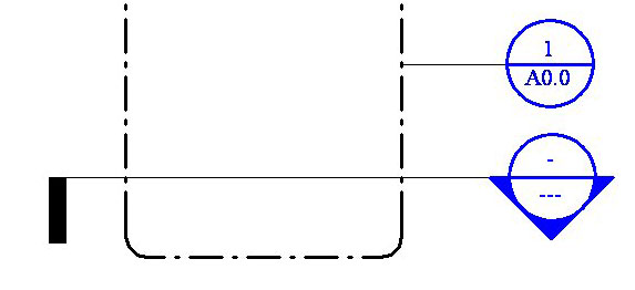
2. Place a building section line and select it. You'll notice two blue circular arrows show up at either end of the section line. Click on it to cycle through section tail types. You'll also notice a blue breakline in the center of the section. Click on it to break the section into segments.

3. Place a building section line and select it. In the options bar you can "Split Segment." Place your cursor anywhere on the section line and start splitting the section line into segments.

4. Sometimes section lines disappear. Right click on the section and you can "Hide annotation in view." Goto the sections properties and you'll notice the parameter "Hide at scales coarser than." If your view is at a scale coarser than the parameter shown then the section annotation will disappear.

5. You can goto Settings... View tags... Section tags... to change the look of building, wall, and detail section annotations. Goto Settings.. View tags... Callout tags... to change the look of detail callouts. You can only choose from loaded Section and Callout Head annotation symbols. Edit those families for more custom heads.

Now a common problem is how do I get a section line EXACTLY where I want it?

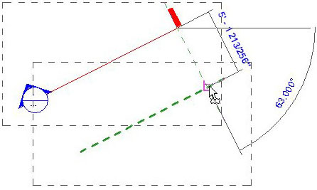
Let's say you wanted a section at a very specific angle and at a very specific place in plan view that is not orthogonal. Just draw a reference plane at the angle you want (and in the location you want for your section line) then place your section line adjacent to the reference plane. The section line will snap to the angle of an adjacent reference plane but won't snap to the reference plane itself. Now, to align your section line with the reference plane the align tool isn't going to work. So, select the move tool, hover over the section tail (revit will snap to the section line), and just move the section from it's present location to the reference plane.

One last thing. If you don't like the look of Revit's Elevation tag you could design your own section head (for use as an elevation tag) and use these modified sections instead of the given elevation tags.

Monday, June 19, 2006

Callout Annotation Features

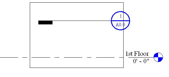
Goto View... Callout. You'll notice you can select a Floor Plan or Detail View callout. Select Detail View and draw a callout in plan view. Select the callout and goto its properties. You'll notice the parameter "Show in" is set to "Parent view only". Change it to "Intersecting views." Now place a building section in plan view that intersects the callout region.

Goto the building section and you'll notice Revit automatically placed a Detail view section annotation.

Wednesday, May 31, 2006

Rooms in a split level environment

Are your room tags not working? Maybe the new room tool could use a little explaining. It sure needed explaining to me.

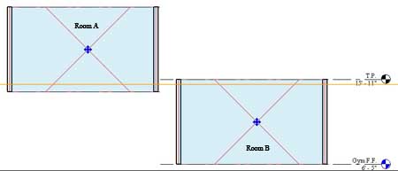
1. The cut plane (orange) of your floor plan view range must cut through ALL the rooms you want to tag in that view. Setting the proper cut plane height is especially critical if you have a split level project.

2. If your cut plane is below the lower limit of a room, tags in that room may only display a ? instead of the room name. If this happens then you'll have to raise your cut plane so that it intersects the room, delete the old room tag, and replace the room tag.

3. If your cut plane is above the upper limit of a room you simply won't be able to tag the room.

4. Once you have your cut plane at a height that intersects the rooms you want to tag THEN you place your plan regions where the cut plane is not properly intersecting windows and doors.

5. Rooms will ignore the cut plane of plan regions.

Wednesday, May 24, 2006

Electrical Symbols

We have a very large residence that requires an overall coordination plan at 1/8" scale and 5 individual quadrants at 1/4" scale because a complete 1/4" scale plan isn't going to fit on a 30x42 sheet.

Well after placing the electrical outlets that come with Revit we noticed that in plan view the outlet symbol doesn't scale when you change the floor plan scale from 1/4" to 1/8". In other words the symbols appear much larger relative to the floor plan when viewed at 1/8" scale. The reason is because the plan view symbol nested in Revit's electrical outlets are Generic Annotations and by design Generic Annotations don't scale when you change a view's scale. Well we wanted the symbols to scale with the floor plan so they wouldn't overwhelm the drawing at 1/8" scale so we drew our outlet symbols as Generic Models instead. Generic Models will scale with the rest of the floor plan.

Now that we've got our outlets and switches scaling the way we like we have a new problem. The text for our Switches (Dimmer, Door-op, Four-way, etc) doesn't show anymore. That's because when we were using nested Generic Annotations, text was supported. Now that we are using nested Generic Models for our electrical symbols text isn't supported. The solution is to create your text in Autocad, import the dwg into your Generic Model, import your Generic Model into your Electrical Family, and there you have it.

Tuesday, March 07, 2006

Dimension Text Override

To override or not to override... Which camp are you in?

Maybe you've noticed that you cannot override dimension text like you would in AutoCAD. You can however add a Prefix and Suffix to dimensions under the dimension's Properties. If you absolutely must override dimension text (for Verify In Field or other common notes) here is what we've done:

1. Select the dimensions tool and goto its properties.
2. Click on Edit/New.
3. Click on Duplicate to create a new Dimension Type.
4. Give the dimension type a new name like... Blank
5. Now Change the text size to 1/256" (smallest you can get)
6. Change Units Format to Decimal Feet and rounding to 0 decimal places. You now have a font that is so small it won't register.
7. Now just use the Text tool to add whatever text you need on top of your "blank" dimension.

Friday, February 03, 2006

The Character Map

You can find the following characters in Window's Character map (Start... Programs... Accessories... System Tools) and add them to your template for easy access:

Degrees °
Diameter Ø
Plus/Minus ±
1/4 stacked ¼
1/2 stacked ½
3/4 stacked ¾
1/8 stacked ⅛
3/8 stacked ⅜
5/8 stacked ⅝
7/8 stacked ⅞
Number №
Bullets ●

Sunday, January 29, 2006

Changing Fonts

Revit's Annotations, Tags, Titleblocks, Schedules, Dimensions, and Text Tool are all setup to Arial by default and there is no one place in Revit to change Font styles and sizes so, like linestyles, you have to kind of search around to find all of them. We use Times New Roman in our office so I had to change the fonts in our template one at a time. Hopefully sharing my experience will help you.

Annotations, Tags and Titleblocks are family files. In your project browser go to Families... Annotation symbols. Here you can right click on any of the loaded families and EDIT them. Once you have the family open just select the text label and go to its properties. Click on Edit/New to change its type parameters. It is then a simple matter of reloading the annotations back into your template file for use in all projects. If you choose to rename your tags you'll have to search around in Settings... Annotations or Settings... View Tags to apply the new families to your template.

Revit's Schedules will, unfortunately, always default to Arial, so you'll have to do the following everytime you create a new schedule. While in the schedule go to View Properties (VP). The fonts are configured under Appearance. (Note: In Revit 9 you can now save a schedule's formatting for use in other projects... While in the project browser right click on the schedule and Save to New File)

Dimensions and Text are fairly simple to change. While in the Dimensions or Text tool just click on the Properties Icon and go to Edit/New. Now you can change the fonts for all your dimension types and all your text types.

If you want to purge unwanted Text or Dimension Styles go to File... Purge Unused... Check None. Then check the objects you want purged from the template. It is important to be aware that the only objects that show up on the purge list are objects that are not currently in use.