The more you work with Revit the more likely you are to run into demons in the data. What do I mean by demons? Demons are unexplained behaviors. I'm not talking about software bugs that won't go away until you've installed a software update. I'm talking about errors in the data of the project file itself. Errors that can be repaired by replacing the corrupt data with an arbitrary value and then changing it back again.
Somehow, the process of changing the offending data to something arbitrary, then changing it back to the way it should be can remedy unexplained behaviors. I'm not talking about changing a value and then hitting the undo command. I'm talking about using Revit's tools to change the data to something arbitrary then changing it back... like the change is some new data for the model. It's just a matter of isolating the parameter values that are causing the unexplained behaviors... then finding the right combination of commands that will reset or refresh the offending data. These commands might include flexing parameters, cut & paste in same place, mirror, nudging, or possibly other commands. Let me give you some examples...
I upgraded a model once, from Revit 2009 to Revit 2011, and an odd thing happened. In hidden line mode, half the doors and windows had shaded glass (by design) while the other half had no shading. And it wasn't like there was any consistency... the shading was gone from random doors and windows. I realized at that point that I had a demon in my data, so I went into the offending material (glass) and set the surface pattern of the glass material to none (it was the surface pattern that was not cooperating), then changed the surface pattern back to solid fill to get this glass material to show properly everywhere.
Another thing that happens a lot... I like to nest families into a host family and link the parameters of the nested family and its host family, but once in a while after making a change to a nested family and loading it back into the host family, solids disappear or just don't flex when the family is loaded into a project. I have to flex some of the linked parameters, while still in the family editor, to reset or refresh the offending data.
Wall cleanups at intersections (not to beat a dead horse) can also cause demons. Sometimes nudging one of the walls can cleanup your intersection. Sometimes you have to cut a wall to your clipboard and paste it back into the same place to get intersections to heal properly. In fact, when any family (that was working fine before) isn't cooperating try a cut and paste in same place. This can reset data in the model.
If any of my readers are familiar with a particular demon please feel free to leave a comment describing the demon and how you "exorcised" it.
Showing posts with label Families. Show all posts
Showing posts with label Families. Show all posts
Friday, July 23, 2010
Wednesday, July 29, 2009
Instance Parameters: The Double Agent
This is going to be particularly helpful to those of you working on large projects. Some of you may already be aware of it, but I haven't seen it documented anywhere so here goes...
I call this technique the Double Agent because the Instance Parameters discussed here will temporarily act like Type Parameters under the right conditions. Why would I want an Instance Parameter to act like a Type Parameter? you ask. Well, quite often, but not always we want to apply the same Instance Parameter value (like a comment that is repeated for MOST instances of a Family Type) to many of the same Doors, Windows, Sheets, or other families. Comments are typically Instance Parameters that you have to change one at a time. But I don't want to change comments one at a time when there are so many of the same comment value. I want them to update once and simultaniously like a Type Parameter would, without having to use a Type Parameter (because I may still want one or two comment values to remain unique. Well, how do you do it? The Answer: With Schedules
Here is the procedure. Go to your door schedule for example.

You'll notice that I have four door types (71,66,17,64). I need to add the Remark 1hr rated to types 66 & 64. Rather than enter the value one field at a time for the Instance Parameter called Remark, lets add the value to all 8 fields once and simultaniously. Here's how.
Go to View Properties... Sorting Grouping... Now make a mental note (or write it down if you wish) of the current Sorting/Grouping settings because, like a good double agent, you're going to have to restore the schedule to its original identity when we're all done. Now change the setting to what you see below. 


These are the rules of the game: You have to sort the schedule by some Type Parameter or by some Instance Parameter with equal values already present.
Now that I have the value 1HR RATED for all of the 1HR doors, lets say I want to change the value to 1.5HR RATED. Just isolate the REMARKS parameter from the Sorting/Grouping settings and exchange the old value for the new value.
So once again, why not just make your Instance Parameter a Type Parameter? Because the Instance Parameter value you choose may not always apply to every instance of a Family Type. This is just a custom way to update multiple fields once and simultaniously.
I hope you'll enjoy exploring the many applications of The Double Agent technique.
I call this technique the Double Agent because the Instance Parameters discussed here will temporarily act like Type Parameters under the right conditions. Why would I want an Instance Parameter to act like a Type Parameter? you ask. Well, quite often, but not always we want to apply the same Instance Parameter value (like a comment that is repeated for MOST instances of a Family Type) to many of the same Doors, Windows, Sheets, or other families. Comments are typically Instance Parameters that you have to change one at a time. But I don't want to change comments one at a time when there are so many of the same comment value. I want them to update once and simultaniously like a Type Parameter would, without having to use a Type Parameter (because I may still want one or two comment values to remain unique. Well, how do you do it? The Answer: With Schedules
Here is the procedure. Go to your door schedule for example.

You'll notice that I have four door types (71,66,17,64). I need to add the Remark 1hr rated to types 66 & 64. Rather than enter the value one field at a time for the Instance Parameter called Remark, lets add the value to all 8 fields once and simultaniously. Here's how.
Go to View Properties... Sorting Grouping... Now make a mental note (or write it down if you wish) of the current Sorting/Grouping settings because, like a good double agent, you're going to have to restore the schedule to its original identity when we're all done. Now change the setting to what you see below.

You can isolate the From Room: Name (or Type Mark parameter). It is very important to uncheck the Itemize every instance option. This is what you'll see.

Now Type in the Remark 1HR Rated for all doors without a room name... then change the Sorting/Grouping setting back to their original state and You'll have added the Value 1HR Rated to the Instance Parameter Remarks for all doors without a room name.

These are the rules of the game: You have to sort the schedule by some Type Parameter or by some Instance Parameter with equal values already present.
Now that I have the value 1HR RATED for all of the 1HR doors, lets say I want to change the value to 1.5HR RATED. Just isolate the REMARKS parameter from the Sorting/Grouping settings and exchange the old value for the new value.
So once again, why not just make your Instance Parameter a Type Parameter? Because the Instance Parameter value you choose may not always apply to every instance of a Family Type. This is just a custom way to update multiple fields once and simultaniously.
I hope you'll enjoy exploring the many applications of The Double Agent technique.
Wednesday, April 25, 2007
Revit News & Resources
The UK Revit Users group is hosting a Revit Design Awards 2007 but you have to work in the UK to enter.
For those of you familiar with Content Highway or other Family File managers there is a new program being exhibited at this years AIA Convention in San Antonio, Texas. It's called techtonic and includes many very attractive features. TechtonicStudio also has a library of 100,000 commercial interior finishes for those of you who do a lot of photorealistic rendering and could use a new source of material maps.
Sometimes visitors to my blog ask me how they can print the blog for future reference. If you have a PDF writer like PDFCreator, CutePDF, or PDF Factory you should be able to print the webpage to PDF.
Some thoughts on Revit
Some people have to be reminded that the project file is a database and like any database the more and accurate information about the project you put into the model the more analytical modeling and scheduling you can get out of the model.
Building highly parametric families that flex can be just as tedious as software programming if you're not familiar with the "programming language" or in this case the many rules and shortcuts for family file creation. The family editor is in essence a "graphical" programming environment. Being more visual, this is probably the perfect programming enviroment for architects. As a rule of thumb the more automation you want to build into family or project files the more skilled your users have to be to modify these files later. Not everyone in the office needs to understand the rules of family file creation to use these families, but they would need some expertise to open these family files and make significant modifications. I know the same is true for many BIM applications.
Autodesk publishes basic usage of the tools in Revit, but there are many clever things an office can do by mixing and matching different tools and parameter values to get the project file to analyze the database and report and illustrate the information you need (and some information you didn't know you needed).
Sunday, March 04, 2007
SpecifiCAD beta for Revit 9.1 released
CADalytic Media has released a beta version of SpecifiCAD. Utilizing the Revit API SpecifiCAD will add the URL and DESCRIPTION of any product on the McGraw Hill Construction Sweets Network website to the Identity Data of any family you choose. This data can then be exported to 3rd party Spec Writing Software.
- Download SpecifiCAD
- Install SpecifiCAD for Revit 9.1
- Open a new project in Revit 9.1
- Goto Tools... External Tools... SpecifiCAD
- Place a component in any view.
- Highlight the component and click on the Specify button in your SpecifiCAD dialog box
- If SpecifiCAD is not finding what you want you can do custom searches
- When you find what you want highlight the component again and click on the LINK button below the product you want.
Thursday, December 21, 2006
Content Highway Beta Released Today
In December 2005 Marek Brandstatter announced the development of Content Highway Desktop, a content management solution for Autodesk Revit that allows you to manage Revit family (RFA) files on your computer and optionally publish them to Content Highway Web for sharing and collaboration.
Many AUGI members were anxiously anticipating the release of this software.
Content Highway was made available today. Download the beta here.
Many AUGI members were anxiously anticipating the release of this software.
Content Highway was made available today. Download the beta here.
Wednesday, October 04, 2006
Materials in Families
When building your families you might notice there are many ways to apply materials to your solids. Here are 4 ways to apply materials and some reasons for using each.
Element Properties
The most obvious method is to extrude a shape... go to its properties and specify a material for your solid form in the Material parameter under the Materials & Finishes group.
Element Properties
The most obvious method is to extrude a shape... go to its properties and specify a material for your solid form in the Material parameter under the Materials & Finishes group.

The Paint Tool
Goto Tools... Paint and you can also paint materials onto individual surfaces like the surface of a pool.
Goto Tools... Paint and you can also paint materials onto individual surfaces like the surface of a pool.
Material Parameters
While in the Family Editor go to Family Types... Add Parameter... and specify a new parameter of Type "Material." Now associate your new parameter to the Material parameter in Element Properties of the solid form (click tiny grey button). Once loaded into a project go to the Family's properties... Edit/New. You can now change the material from Family Type to Family Type. This method is very useful if you're expecting the material to change depending on the Family Type.

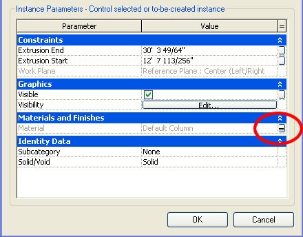
By Category
Extrude a shape... go to its properties and set your material to "By Category." You'll notice a parameter called Subcategory. To add a custom Subcategory go to Settings... Object Styles. After you've created your custom subcategory go back to the elements properties and assign the Subcategory to your solid form. Now when you load your family into a project file you can control materials globally in Settings... Object Styles. This method is very useful if you want to control the palette of your project globally from Object Styles.
Extrude a shape... go to its properties and set your material to "By Category." You'll notice a parameter called Subcategory. To add a custom Subcategory go to Settings... Object Styles. After you've created your custom subcategory go back to the elements properties and assign the Subcategory to your solid form. Now when you load your family into a project file you can control materials globally in Settings... Object Styles. This method is very useful if you want to control the palette of your project globally from Object Styles.

Tuesday, September 26, 2006
Ductwork and Flues
Found an interesting feature in sweeps today. Create a sweep with an arched path. Go to the sweeps properties and you'll notice two parameters (Trajectory Segmentation & Maximum Segment Angle). Set the Trajectory Segmentation to true and choose a maximum segment angle. You now have yourself ducts and flues in Revit Building.
Friday, September 22, 2006
Loading Libraries
Goto File... Load from Library... Load Family and you'll notice icons on the left for Desktop, My Documents, My Computer, My Network Places, Imperial Library, Imperial Detail Library, and Training Files. Many beginners don't know that one can add to and customize this list of icons. Just goto Settings... Options... File Locations and add as many Libraries as you like.
To make loading families faster add a hotkey (like FF for Family Files) to the keyboardShortcuts.txt file:
"FF" menu:"File-Load from Library-Load Family"
NOTE: This tip can also be used for quickly loading project files. Go to File... Open and you'll see the same icons so you can add all your project directories too.
Wednesday, September 20, 2006
Family Templates
Let's say you have an office standard for how doors and windows should appear in plan view and you want to incorporate this or any other standard as part of your door and window templates. Here are a few things you should know:
1. Save your templates under a new name so users still have access to the door and window templates that ship with Revit.
2. To edit a template change it's file extention from .rft to .rfa.
3. Anything you place in the template can not be deleted once you open the template as a new family file (File... New... Family) so don't try to create new templates this way. Instead you should create new templates by changing an existing template file extention from .rft to .rfa and saving the template under a new name.
Tuesday, September 12, 2006
Head & Sill Height Behavior
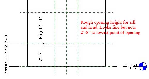
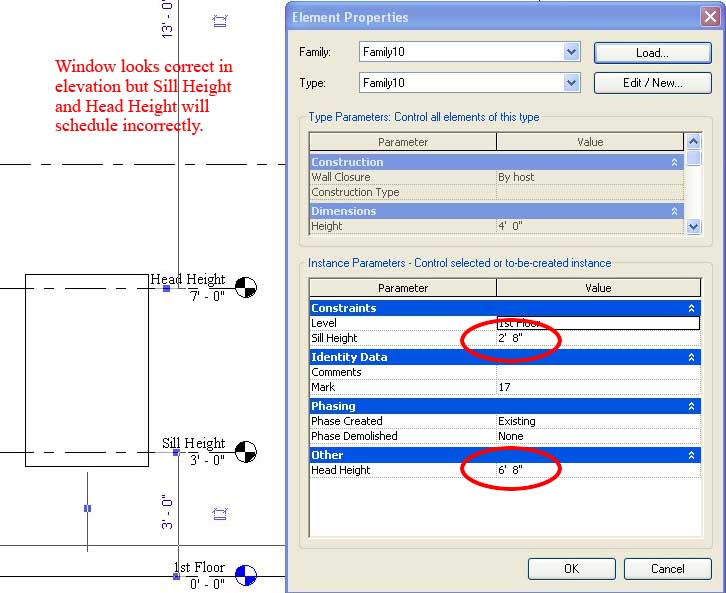
Did you model a rough opening height for your window that has say a sloping sill and now your head height is not accurate in your schedule? This is why.
We've recently discovered that the Head Height instance parameter in a door or window family is calculated from Sill Height + Height (easy right? wrong). It's not the Default Sill Height parameter as you would expect but rather the lowest point of your geometry that defines the Sill Height Revit uses to calculate Head Height (Head Height = 2'-8" + 4'-0" but should be 3'-0" + 4'-0") .
We've recently discovered that the Head Height instance parameter in a door or window family is calculated from Sill Height + Height (easy right? wrong). It's not the Default Sill Height parameter as you would expect but rather the lowest point of your geometry that defines the Sill Height Revit uses to calculate Head Height (Head Height = 2'-8" + 4'-0" but should be 3'-0" + 4'-0") .
Monday, August 28, 2006
Wall Layer Wrapping Control
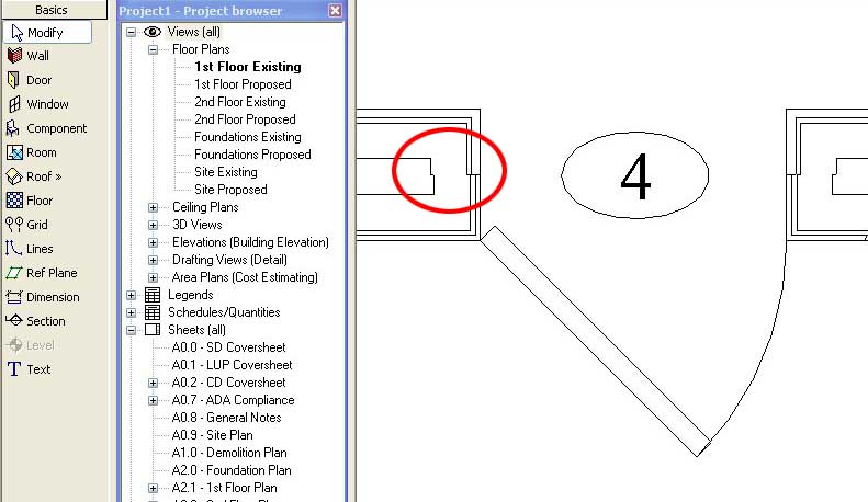
Let's say you've set your wall type parameter "Wrapping at Inserts" to Both because you want the exterior and interior finishes to wrap (as shown below).
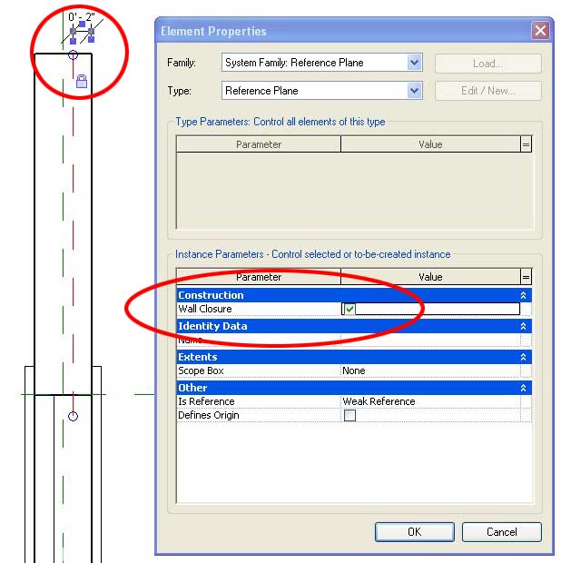
But you'll notice that by default Revit will wrap your layers to the centerline of the wall. I just discovered that you can adust where the wall wraps to. First thing you have to do is open the door (or other) family and add a reference plane (as shown below). Now select that reference plane and make sure that under its properties you change the Wall Closure parameter to TRUE. Lastly, add a dimension (like say 2 inches) and lock the dimension so that your reference plane is always 2 inches from your face of wall.
Now load your door family into a project and place it in a wall. Make sure the wall's Wrapping at Inserts parameter is set to Both. You'll notice that you can now control the location of wall layer wrapping.
You can also add a second reference plane to control exterior and interior wall layer wrapping separately.
But you'll notice that by default Revit will wrap your layers to the centerline of the wall. I just discovered that you can adust where the wall wraps to. First thing you have to do is open the door (or other) family and add a reference plane (as shown below). Now select that reference plane and make sure that under its properties you change the Wall Closure parameter to TRUE. Lastly, add a dimension (like say 2 inches) and lock the dimension so that your reference plane is always 2 inches from your face of wall.
Now load your door family into a project and place it in a wall. Make sure the wall's Wrapping at Inserts parameter is set to Both. You'll notice that you can now control the location of wall layer wrapping.
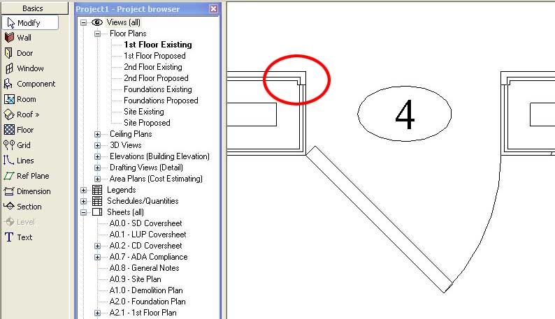
You can also add a second reference plane to control exterior and interior wall layer wrapping separately.
Wednesday, July 19, 2006
Parametric Column Families
Have you tried everything and you can't get your column to stretch parametrically?
It can be a difficult task to figure out. There is no way to scale a column globally so that the proportions of your beautiful column are preserved (wishlist item alert) but we can show you how to build simpler columns that stretch properly.
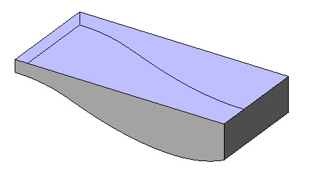
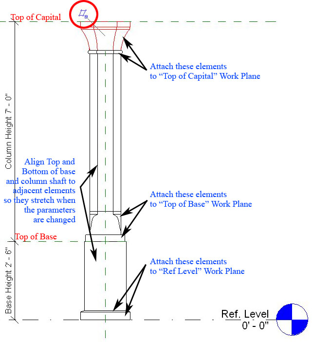
The example below is an adjustable column with adjustable base.
First thing you need to setup are reference planes. We have the given Ref Level and we've created a Top of Base and Top of Capital. Remember to goto the plane's properties and give each plane a unique name (we will use this later). Dimension these planes and attach your parameters (as shown below).
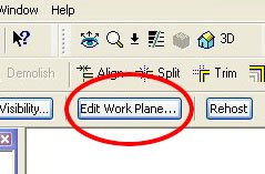
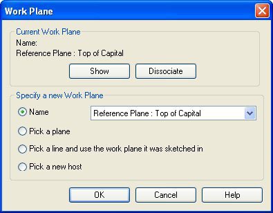
Second you have to create each of your elements for base and capital. Now the trick is that after you've created your elements you have to Edit the work plane of each element so that the elements are attached to the reference plane you would like them to "travel with." when adjusting the height parameters.
In this example we've attached our elements to Ref Level, Top of Base, and Top of Capital (as shown below).
It can be a difficult task to figure out. There is no way to scale a column globally so that the proportions of your beautiful column are preserved (wishlist item alert) but we can show you how to build simpler columns that stretch properly.
The example below is an adjustable column with adjustable base.
First thing you need to setup are reference planes. We have the given Ref Level and we've created a Top of Base and Top of Capital. Remember to goto the plane's properties and give each plane a unique name (we will use this later). Dimension these planes and attach your parameters (as shown below).
Second you have to create each of your elements for base and capital. Now the trick is that after you've created your elements you have to Edit the work plane of each element so that the elements are attached to the reference plane you would like them to "travel with." when adjusting the height parameters.
In this example we've attached our elements to Ref Level, Top of Base, and Top of Capital (as shown below).

Now load your column into a project and place it on the 1st and 2nd floors to make sure that the elements are correctly placed and stretch properly in both scenarios.
Tuesday, June 13, 2006
More Revit Content
Form Fonts is a new subscription service offering Revit content.
Revit Drop is another subscription service with some free content.
CadPlan has content if you don't mind that it's in metric.
SaleSoft has a content library also in metric.
Revit Drop is another subscription service with some free content.
CadPlan has content if you don't mind that it's in metric.
SaleSoft has a content library also in metric.
Wednesday, May 24, 2006
Electrical Symbols
We have a very large residence that requires an overall coordination plan at 1/8" scale and 5 individual quadrants at 1/4" scale because a complete 1/4" scale plan isn't going to fit on a 30x42 sheet.
Well after placing the electrical outlets that come with Revit we noticed that in plan view the outlet symbol doesn't scale when you change the floor plan scale from 1/4" to 1/8". In other words the symbols appear much larger relative to the floor plan when viewed at 1/8" scale. The reason is because the plan view symbol nested in Revit's electrical outlets are Generic Annotations and by design Generic Annotations don't scale when you change a view's scale. Well we wanted the symbols to scale with the floor plan so they wouldn't overwhelm the drawing at 1/8" scale so we drew our outlet symbols as Generic Models instead. Generic Models will scale with the rest of the floor plan.
Now that we've got our outlets and switches scaling the way we like we have a new problem. The text for our Switches (Dimmer, Door-op, Four-way, etc) doesn't show anymore. That's because when we were using nested Generic Annotations, text was supported. Now that we are using nested Generic Models for our electrical symbols text isn't supported. The solution is to create your text in Autocad, import the dwg into your Generic Model, import your Generic Model into your Electrical Family, and there you have it.
Monday, May 01, 2006
Upgrading Families
Our family library has grown considerably and we were tired of seeing "THIS IS A ONE TIME UPGRADE PROCESS ONLY" every time we opened a family file that was saved in Revit 8.1.
Well, Autodesk has a Family Upgrade Utility for upgrading all of your old family files to the new version. Make sure you backup your library before trying this. This also doesn't work over a network so you'll have to copy your library to your local harddisk before executing the procedure.
Well, Autodesk has a Family Upgrade Utility for upgrading all of your old family files to the new version. Make sure you backup your library before trying this. This also doesn't work over a network so you'll have to copy your library to your local harddisk before executing the procedure.
Saturday, April 01, 2006
Door & Window Tips
There is a lot one can learn about the family editor. I'll just briefly describe what it is and what tips will help you get started with creating custom doors and windows.
The family editor is where one models complex geometries such as door families, window families, furniture families, custom annotations, fireplaces, etc. The tools available in the family editor are somewhat different than those available in a project file. In a family you can place detail components, symbols, and model lines just as you would in a project file, but you can also place nested families, symbolic lines, and parametric parameters. A nested family is simply a family loaded into another family. If you're in the habit of loading nested families be sure and purge unused nested families before you load a family into your project file (to keep the file size down).
There are two ways to work in the family editor. Create a family file that is separate from the project file (go to File... New... Family) or build an in-place family (go to Modelling... Create). We only use in-place families for some sitework and some building details. Mostly we generate family files. Family files (.rfa) can be saved for use in other projects. Building a library of family files will save you time on future projects.
If you're going to build a door, window, or other family you'll probably want to start with one of the templates Revit offers (go to File... New... Family and choose the appropriate template). These are a few tips I'd recommend:
1. The first place I always go to after starting a door or window family is the Family Type. Here you can change parameters for width and height which are already setup for you. One family file could have many types. A type is defined by its parameter values. If you want one family type to be 3' x 3' and the other to be 3' x 4' then you'll want to create NEW family types and name them according to the parameters that change (size in this case).
2. In a door or window family template select the reference plane that is centered in the family and go to it's properties. You'll notice that the parameter "Is Reference" is called out as "Center (Left/Right)". This is the reference plane that Revit uses when you're dimensioning to the centerline of your doors and windows in plan. Always try to keep this reference plane centered in your family or you'll have problems further down the road when you want to dimension to centerline of door or window. Checking for this is something beginners often overlook to do.
3. In plan view you'll notice that the Exterior and Interior are marked. Always keep in mind which side is which when you're building your window or door. You'll also notice a Flip Control (two blue arrows). Don't delete this annotation as you may want to flip the door or window direction after placing it in your project.
4. If you want your door or window to stretch properly when you change it's width or height in the Family Types first setup reference planes that define the basic geometry of your door or window and dimension them (with parameters if you want them to stretch). Then you should dimension or align your solid shapes to the established reference planes or lines so that the modelled shapes will stretch with the planes. I would recommend you take a look at "Casement 2x3 with Trim.rfa" in the Imperial Library as an example of a window that stretches properly.
5. Always check to see that your family stretches properly in x, y AND z axis. One thing you can do to make sure your door or window will work in walls of differing thicknesses is to select the wall in your family template and change its structure from 6" to maybe 10" (go to the walls Properties... Edit/New... Structure). Checking this behavior is something beginners often overlook to do.
6. If you want the correct width, height, and sill height to show up in the door and window schedules I recommend you dimension these basic parameters in your doors and windows. What happens too often is when a user is in a hurry to make a door or window he/she ignores dimensioning these parameters and the schedule will read whatever width and height are established in Family Types (whether they are right or not). You'll end up with the wrong height and width in your schedule if you don't at least dimension these basic parameters. To assign a parameter to a dimension simply select the dimension and change its Label from "None" to the desired parameter.
For more on families see Working with Autodesk Revit Components
Friday, March 10, 2006
Family Visibility Control
When creating a door or other family we find that when loaded into a project we sometimes like to be able to switch on and off parts of the family but not the whole family. We have found three ways to accomplish this.
Visibility: We like to use symbolic lines to represent doors and windows in plan so we like to turn off the visibility of our model objects (glass and panel) in plan view. While in your family editor, this is simply done by selecting the object you want to hide and clicking on the Visibility button in your tool bar above. Note that this method is for turning off objects that you NEVER want to see in plan, section, elevation, or at specific Detail Levels.
Object Styles Subcategory: Another way to control the visibility of parts of a family is to setup new subcategories. While in your family editor goto Settings... Object Styles. From here you can add subcategories. Now select an object in your family and goto its properties. You'll notice that you can change the object's Subcategory. Load your new family into a project. You can now control the visibility of parts of your family GLOBALLY under Settings... Object Styles or in a SPECIFIC VIEW under View... Visibility/Graphics.
The Yes/No Parameter: While in the family editor goto Family Types... Add Parameter... And create a new Type parameter with Type (Yes/No). Now finish the Family Type and select any object in your family. Goto it's properties and you'll find a Visibility check box. At the far right there is a tiny grey box. Click on it and select your new Yes/No Parameter as the parameter that defines the visiblity. Now exit the element properties and go back into the Family Types. From here you can control the visibility of the object. Just add two new family types and uncheck the new parameter in one type while leaving it checked in the other type. The object will appear grey while in the family editor, but once you load the family into a project you will find that you can now switch on or off part of the family by switching between family types.
Friday, February 10, 2006
Changing Family Categories
Let's say you started to create a storefront (with door) using the door family template and now you want it to schedule as a window instead. While in the family editor go to Settings... Family Category and Parameters... and just switch to another compatible family. Now when you import your storefront it will schedule with all the other windows.
Subscribe to:
Posts (Atom)