The more you work with Revit the more likely you are to run into demons in the data. What do I mean by demons? Demons are unexplained behaviors. I'm not talking about software bugs that won't go away until you've installed a software update. I'm talking about errors in the data of the project file itself. Errors that can be repaired by replacing the corrupt data with an arbitrary value and then changing it back again.
Somehow, the process of changing the offending data to something arbitrary, then changing it back to the way it should be can remedy unexplained behaviors. I'm not talking about changing a value and then hitting the undo command. I'm talking about using Revit's tools to change the data to something arbitrary then changing it back... like the change is some new data for the model. It's just a matter of isolating the parameter values that are causing the unexplained behaviors... then finding the right combination of commands that will reset or refresh the offending data. These commands might include flexing parameters, cut & paste in same place, mirror, nudging, or possibly other commands. Let me give you some examples...
I upgraded a model once, from Revit 2009 to Revit 2011, and an odd thing happened. In hidden line mode, half the doors and windows had shaded glass (by design) while the other half had no shading. And it wasn't like there was any consistency... the shading was gone from random doors and windows. I realized at that point that I had a demon in my data, so I went into the offending material (glass) and set the surface pattern of the glass material to none (it was the surface pattern that was not cooperating), then changed the surface pattern back to solid fill to get this glass material to show properly everywhere.
Another thing that happens a lot... I like to nest families into a host family and link the parameters of the nested family and its host family, but once in a while after making a change to a nested family and loading it back into the host family, solids disappear or just don't flex when the family is loaded into a project. I have to flex some of the linked parameters, while still in the family editor, to reset or refresh the offending data.
Wall cleanups at intersections (not to beat a dead horse) can also cause demons. Sometimes nudging one of the walls can cleanup your intersection. Sometimes you have to cut a wall to your clipboard and paste it back into the same place to get intersections to heal properly. In fact, when any family (that was working fine before) isn't cooperating try a cut and paste in same place. This can reset data in the model.
If any of my readers are familiar with a particular demon please feel free to leave a comment describing the demon and how you "exorcised" it.
Showing posts with label Visibility. Show all posts
Showing posts with label Visibility. Show all posts
Friday, July 23, 2010
Friday, April 16, 2010
Should I enable Hardware Acceleration?
Hardware Acceleration (in options) controls the performance of several features in Revit 2011 including:
- realistic materials in realistic view
- ambient occlusion
- performance of mechanical views
- performance of underlay views
- performance of overall project
Thursday, August 20, 2009
Additive Views vs. Subtractive Views
Common Problem: When I place an electrical fixture or other family category it pops up automatically in other views I would rather not see it in.
Reason: In the default Revit tempate almost every category is unnecessarily turned on in all views so the same family shows up everywhere.
Solution: Create Additive Views instead of Subtractive Views for family categories that are only used in one or two views. By that I mean, start with most family categories turned off in your new view's visibility/graphics and gradually add the categories that you want to see.
Extra Tip: If you want future new views to be additive by default, create a view template. Then, when you apply the template to a view, check the option that reads "Apply automatically to new views of the same type."

Tuesday, November 11, 2008
Using Radar
What is Radar?
Radar is a method of detecting distant objects and determining their position.
Radar is a method of detecting distant objects and determining their position.
When do I need it?
You just linked a developed Revit model into a new project file and you can't seem to find it. Ever happen to you? I know it happens to many. This is where having radar comes in handy.
You just linked a developed Revit model into a new project file and you can't seem to find it. Ever happen to you? I know it happens to many. This is where having radar comes in handy.
If I just imported a project and I can't seem to locate the imported model the first thing I do is setup my radar.
1. Go to a floor plan view and add four new elevations looking in all directions.


2. Highlight these new elevations in your project browser and go to element properties.
3. Uncheck Crop View and Far Clip Active parameters.
3. Uncheck Crop View and Far Clip Active parameters.
4. Open each view individually and zoom all (ZA) until you find the model you are looking for.
Users new to file linking can waste valuable time searching for imported models. Next time just tell them to setup their radar.
Tuesday, March 06, 2007
Open, Sesame
When you place an existing door or window in an existing wall and then demo the door or window in the new construction phase Revit automatically places an infill wall to replace the door or window. You can then change this infill wall type to any wall type you like, but without a workaround you really can't get rid of the infill wall. We frequently run into situations where we want to demo a door but leave the opening intact. I have seen this discussed at length on AUGI and there are many workarounds but I think the workaround I found today (One Thousand and One Nights later) is an easier option.
Revit has had a Filter function since release 9. By adding a Comment to any instances of infilling walls and filtering out the visibility of the walls based on the Comment added you can hide infilling walls from any of your views.
Revit has had a Filter function since release 9. By adding a Comment to any instances of infilling walls and filtering out the visibility of the walls based on the Comment added you can hide infilling walls from any of your views.
- Place an existing wall and door in any existing plan view.
- Demo your door in the new construction phase.
- Select the infill wall and add a value to the Comments instance parameter under element properties.
- Go to the Filters tab in the Visibility/Graphic Overides of your new construction view.
- Define a new filter for Walls and select Filter by: Comments... equals. Type in the value you used in the Comments field earlier.
- Insert your new Filter into this view's Visibility/Graphics and turn off its visibility. Do the same for all views where you would like to hide infill walls.
- Unjoin the geometry of the infill wall and its host wall if you can't see where they meet in 3D or elevation views.
Monday, March 05, 2007
Filtering View Specific Content
Do you want to know if Text Backgrounds used in a view are opaque or transparent?
Are you trying to find hidden filled regions in a view?
Are you having trouble distinguishing detail lines from model lines in a view?
Well, the easiest way to separate view specific content from model content in a view is to place a temporary filled region with a Solid Fill Pattern that covers the entire view (choose a neutral color). Then just select the filled region and Send To Back. All view specific content will pop out and all model content will be hidden behind your Filled Region.
However, if you want to know where the Linework Tool was used you'll have to resort to selecting the Linework Tool... By Category... and floating your mouse over the model to "scan" for where it may have been used. Lines will highlight when you roll your mouse over them if the Linework Tool was infact used.
Friday, January 12, 2007
Hide & Seek (updated)
Did something in your project disappear?
- First, check to see if it is still visible in other views.
- Check Visibility/Graphics. Is the object category (and subcategories) ON?
- Check Visibility/Graphics. Is the linestyle set to Override?
- Check Visibility/Graphics. Is the detail level set to By View?
- Check Visibility/Graphics. Are all the worksets ON?
- Check Visibility/Graphics. Are all the filters ON?
- Check Visibility/Graphics. If the object is in a linked file check Revit Links.
- Check Visibility/Graphics. Check each design option.
- Try changing phase and phase filter in View Properties (VP).
- Try changing the detail level of the view.
- Are all your worksets opened? (it may be hiding in a closed workset).
- Check View Range in View Properties (VP).
- Check for Plan Regions if in a floor plan view.
- The object may have been moved to a new elevation.
- Check Crop Region and Far Clip settings in View Properties (VP).
- Set your view to wireframe. It may be hiding behind a filled region or other object.
- Select the Linework tool (set to By Category) and see if it wasn't hidden with this tool. It would be very benefitial if one could toggle on/off the use of the linework tool in a view.
- If the problem is with a family file open the family and check the visibility of the elements.
If you can't find it by now it was probably deleted.
Saturday, October 21, 2006
Instant Section Box
Scott Brown posted this on Zoogdesign ages ago but I thought it was pretty useful so I'll post it. While in plan view draw a floor plan callout... Go to any 3D view... Go to View... Orient... To Other View... and select your floor plan callout from the list of views. Rotate your view and you'll notice it's an instant section box. Very cool.
Wednesday, September 27, 2006
Surveys and Site Plans
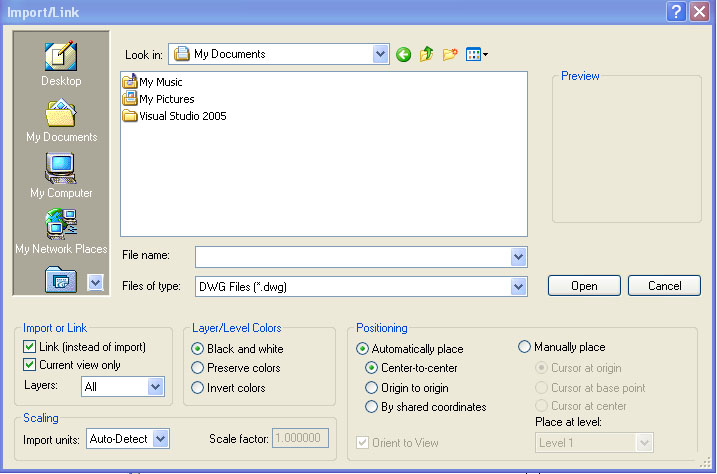
We quite often import survey data into Revit from DWG files given to us by the surveyor. Here are a few tips to consider when importing (and exporting) surveys.
2. If you check "Current view only" your survey will only show in the active view (similar to detail lines). If you uncheck "Current view only" your survey will be visible in all of your views... elevations, sections, 3D views, etc (similar to model lines) and you'll have to adjust its visibility one view at a time.
3. Now let's say you've developed your site plan (with linked survey) and you want to export the data (including survey) back to DWG format. If you go to File... Manage Links... and Import your linked survey then it will export with the rest of your model to DWG format. If you don't Import your survey you'll notice that only revit components will export. The survey needs to be a part of the Revit model or Revit won't consider it when exporting your site plan to DWG.
UPDATE (09/27/06):
In Revit Building 9.1, when a DWG or DXF survey file is imported with the Current View Only checkbox checked, you cannot select the DWG/DXF instance to create a terrain model from the instance like you could with 9.0 and earlier versions. So imported data to be used for creating a toposurface must be imported with the Current View Only checkbox cleared. Thanks to Wes Macaulay on AUGI for posting this issue. Doesn't look like Autodesk is going to change this behavior.
Saturday, July 22, 2006
Stepped Foundation Plans
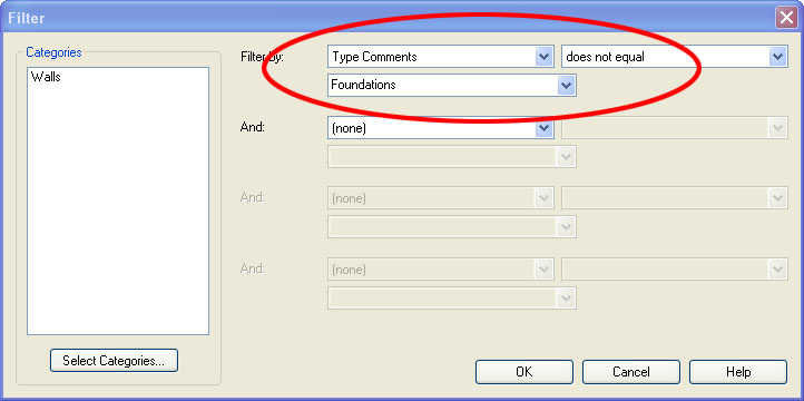
We often have split level projects and we've had a lot of trouble isolating the stem walls and footings from the rest of the model for use in a foundation plan... that is until Revit 9.0 came along. You can now use Revit Filters to isolate your foundation from the rest of your project.
1. Duplicate your Basic Wall: Foundation - 12" Concrete for each stem wall and footing size you need. You could use a Continuous Footing for your footings but we avoid Continuous Footings because their intersections don't clean up as nicely as Basic Walls.
2. Add the Type Comment "Foundations" for each of your new walls. Go to the wall's properties... Edit/New... Type Comments.
5. In Visibility/Graphics go to Model Categories and uncheck everything except Detail Items and Walls.
You can also use phases or worksets to isolate foundations, but we prefer the filter method.
1. Duplicate your Basic Wall: Foundation - 12" Concrete for each stem wall and footing size you need. You could use a Continuous Footing for your footings but we avoid Continuous Footings because their intersections don't clean up as nicely as Basic Walls.
2. Add the Type Comment "Foundations" for each of your new walls. Go to the wall's properties... Edit/New... Type Comments.

5. In Visibility/Graphics go to Model Categories and uncheck everything except Detail Items and Walls.

You can also use phases or worksets to isolate foundations, but we prefer the filter method.
Tuesday, July 11, 2006
View Range & Visibility Lessons
We ran into two interesting View Range problems today.
Interior elevation tags from the first floor plan were mysteriously showing up on the second floor plan. That's because if the top of the crop region for an interior elevation view intersects the primary range (bottom clip plane) of the floor plan above, then the interior elevation symbol will show in the floor plan above. So you have to either lower the top of the interior elevation's crop region or you have to raise the bottom clip plane of the primary range in the floor plan above. Thanks to Steve Valenta on AUGI for pinpointing the exact solution.
While in the second floor plan we underlayed the 1st floor plan but the 1st floor plan walls were not visible while doors, windows, and fixtures were. That's because if the top of the wall below intersects the primary range (bottom clip plane) of the floor plan above, then Revit won't include the walls in the underlay. So we had to raise the bottom clip plane which shouldn't have been below the floor level anyway.
Wednesday, May 31, 2006
Rooms in a split level environment
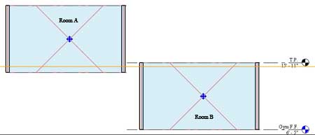
Are your room tags not working? Maybe the new room tool could use a little explaining. It sure needed explaining to me.
1. The cut plane (orange) of your floor plan view range must cut through ALL the rooms you want to tag in that view. Setting the proper cut plane height is especially critical if you have a split level project.
1. The cut plane (orange) of your floor plan view range must cut through ALL the rooms you want to tag in that view. Setting the proper cut plane height is especially critical if you have a split level project.

2. If your cut plane is below the lower limit of a room, tags in that room may only display a ? instead of the room name. If this happens then you'll have to raise your cut plane so that it intersects the room, delete the old room tag, and replace the room tag.
3. If your cut plane is above the upper limit of a room you simply won't be able to tag the room.
4. Once you have your cut plane at a height that intersects the rooms you want to tag THEN you place your plan regions where the cut plane is not properly intersecting windows and doors.
5. Rooms will ignore the cut plane of plan regions.
Monday, May 15, 2006
Coarse, Medium, and Fine - Wall Patterns
You might notice that wall patterns disappear when you're switching between Coarse, Medium, and Fine detail levels.
Let's say you want to show your view (plan/section) in Coarse detail level:
To edit the pattern select the wall...
go to the wall's properties... and Edit/New...
Here you can change the Coarse Scale Fill Pattern parameter.
Now let's say you've switch your view to Medium or Fine detail level:
To edit the pattern select the wall...
go to the wall's properties... and Edit/New...
edit the structure...
and select your new material...
Here you can select your new cut pattern from available fill patterns.
I'm not sure why parameters for Revit's coarse, medium, and fine detail levels cut pattern settings are separated but this is a common question so I thought I'd post the answer.
Monday, March 27, 2006
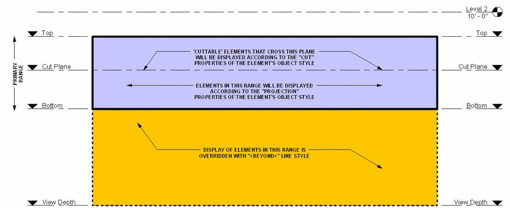
View Range
The use of View Range can be a difficult concept to grasp. The image below has been circulated around and explains how CUT, PROJECTION, and BEYOND linestyles are used by the View Range tool found in View Properties (VP) and Plan Region Properties.
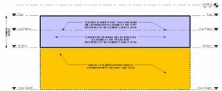
CUT and PROJECTION linestyles are controlled globally in Settings... Object Styles and for each view in Visibility/Graphic Overrides (VG). BEYOND linestyle is controlled globally in Settings... Line Styles and for each view in Visibility/Graphic Overrides (VG).
CUT and PROJECTION linestyles are controlled globally in Settings... Object Styles and for each view in Visibility/Graphic Overrides (VG). BEYOND linestyle is controlled globally in Settings... Line Styles and for each view in Visibility/Graphic Overrides (VG).
Tuesday, March 21, 2006
Floor Plan Backgrounds
Let's say you're doing your own mechanical, electrical, structural or other drawings that require a floor plan that is greyed or halftone (a background). We've found two ways to accomplish this:
Display Model As Underlay: The easiest way is to Duplicate your Proposed Floor Plan view (without Detailing) This is done by right clicking on your floor plan view in the project browser and selecting Duplicate. Now go to the View's Properties and you'll notice a Display Model parameter. By default this is set to Normal. Switch this to As Underlay. Now you can add your view specific tags, annotations, symbols, detail lines, etc. on top of the model. Unfortunately your lighting, furniture, electrical and other families will also be greyed out. If you need to show some model elements Normal then it's on to the next approach.
Visibility/Graphics Halftone: Duplicate your Proposed Floor Plan view (without Detailing) This is done by right clicking on your floor plan view in the project browser and selecting Duplicate. Now go to the view's Visibility/Graphic Overrides (VG). Under Model Categories select ALL. Now unhighlight Electrical Fixtures and Lighting Fixtures and check the Halftone box for one of the highlighted categories. Notice all the highlighted categories are now set to halftone. Click OK. You now have a floor plan background for your lighting and electrical work. Do the same for Detail Items, Electrical Equipment, Plumbing Fixtures, Furniture, Structural Framing, etc. for other disciplines. Go to View... Save as View Template... and you can save these changes to a View template for use in all your projects. To further configure View Templates go to Settings... View Templates.
To transfer View Templates and other standards from your project to a template file see Jay Polding's Importing Wall Styles.
Friday, March 10, 2006
Family Visibility Control
When creating a door or other family we find that when loaded into a project we sometimes like to be able to switch on and off parts of the family but not the whole family. We have found three ways to accomplish this.
Visibility: We like to use symbolic lines to represent doors and windows in plan so we like to turn off the visibility of our model objects (glass and panel) in plan view. While in your family editor, this is simply done by selecting the object you want to hide and clicking on the Visibility button in your tool bar above. Note that this method is for turning off objects that you NEVER want to see in plan, section, elevation, or at specific Detail Levels.
Object Styles Subcategory: Another way to control the visibility of parts of a family is to setup new subcategories. While in your family editor goto Settings... Object Styles. From here you can add subcategories. Now select an object in your family and goto its properties. You'll notice that you can change the object's Subcategory. Load your new family into a project. You can now control the visibility of parts of your family GLOBALLY under Settings... Object Styles or in a SPECIFIC VIEW under View... Visibility/Graphics.
The Yes/No Parameter: While in the family editor goto Family Types... Add Parameter... And create a new Type parameter with Type (Yes/No). Now finish the Family Type and select any object in your family. Goto it's properties and you'll find a Visibility check box. At the far right there is a tiny grey box. Click on it and select your new Yes/No Parameter as the parameter that defines the visiblity. Now exit the element properties and go back into the Family Types. From here you can control the visibility of the object. Just add two new family types and uncheck the new parameter in one type while leaving it checked in the other type. The object will appear grey while in the family editor, but once you load the family into a project you will find that you can now switch on or off part of the family by switching between family types.
Thursday, March 02, 2006
Phases & Phase Filters
Are you doing a remodel project? You’ll need to learn about phases. There are 3 dialog boxes you’ll have to become more familiar with.
1. Phase Settings: Under Settings... Phases... you will find Project Phases, Phase Filters, and Graphic Overrides.
Project Phases: Here you can add new phases to the project. The best practice is to set these up before you begin work on your project. Later Phases are ok to add at a later date but you cannot rearrange the order of phases after entering them. Revit is setup by default with Existing and New Construction phases.
Phase Filters: Here you can control the graphics used for objects who’s relative phases are set to New, Existing, Demolished, or Temporary. Phase Filters will determine whether the Category’s Object Styles are used or whether Revit will use the Graphic Overrides established under the Graphic Overrides tab. You should leave these alone until you grasp an understanding of them.
2. View Properties: Every View has View Properties (VP). In the view properties you will find the Phase and Phase Filter used for that particular view. It is very important that you setup duplicate views for each phase (Existing and New Construction).
Phase: Revit’s views are setup by default with the New Construction Phase. This simply means that all objects placed in this view will automatically be set to New Construction and will show. If you plan on using a remodel project to learn Revit (or teach someone Revit) make sure you setup all the view's phases to Existing before you start. This way you don’t have to think about what phase you’re placing an object in and you won’t have to switch all of the objects from New Construction to Existing after the model has progressed. Once you’re ready to move on to the addition then you can add new views and set their phases to New Construction.
Phase Filter: Revit’s views are setup by default with Show All phase filter. We typically change this to Show Complete. The chosen phase filter will determine how objects that are New, Existing, Demolished, or Temporary (relative to the active phase) will display. Goto Settings... Phases... Phase Filters to view and modify how phase filters affect the display of objects.
3. Object Properties: Under the properties of most objects you will find Phase Created and Phase Demolished.
Phase Created: In what phase was the object created? For example, when you place an object into a view that is set to the Existing Phase the object's properties will automatically reflect that the object was created in the Existing Phase. If the view’s phase is set to Existing and you change the object’s Phase Created to New Construction the object is still there but will disappear from view because the view is setup to only show objects placed in the Existing Phase.
Phase Demolished: In what phase was the object demolished? Very simply if you demolish an Existing object in the New Construction phase the object will display as dashed lines in views who’s phases are set to New Construction. However, the object will still display as whole in views who’s phases are set to Existing.
Friday, February 17, 2006
Plan Regions
Do you have windows that don't show in plan view because they are too high above the cut plane? Do you have a fireplace opening that doesn't show because it's too far below the cut plane? Use the Plan Region Tool in your View Tool Palette. With this tool you can set a unique view range to include objects above or below the cutting plane that's set in the given view.
Once plan regions are placed they can often be difficult to locate. Select one you can find and Edit it. You'll notice that all the other plan regions are now visible.
Once plan regions are placed they can often be difficult to locate. Select one you can find and Edit it. You'll notice that all the other plan regions are now visible.
Subscribe to:
Posts (Atom)