Showing posts with label Walls. Show all posts

Saturday, April 10, 2010

Often Overlooked By Beginners (Part 2)

One of my earliest posts focused on little tools that are often overlooked by beginners. I thought I'd revisit this topic now that I've had more experience working with Revit Beginners. Here are a few more tips that beginners are often not aware of:

1. Wall Location Lines. The location line is kind of an anchor point for a wall. When you flip a wall (ie. change its orientation) the wall will flip about its location line. So if you wanted to flip a wall without affecting its position you could make the wall's centerline its location line as well. Location line is controled in a wall's Instance Properties. Some of your choice settings for the location of the location line include face of core, face of finish, wall centerline, etc. When a wall is selected you might notice two blue dots at either end of the wall. Grab this blue dot and stretch the wall to any length you want. You might also notice that when you change the location line of a wall this blue dot will relocate, reflecting your newly chosen location line.
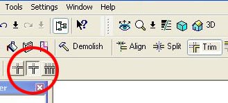
2. How do I fillet two walls (or lines). A common thing for beginners, is to go right to the trim tool in search of a fillet option (because they are likely more familiar with AutoCAD). Well in Revit the fillet tool is located elsewhere. If you are drawing a wall or a line there is a pallet of line shapes that you can draw (square, polygon, circle, arc, etc.) Well fillet is one of those options circled below.


3. Stretching a gridline in the current view only. When working with gridlines for the first time a beginner will often take notice that stretching the end bubble of a gridline stretches the grid in all views globally. The next question they ask is, "How can I stretch it for this view only?" Well there is a little icon next to a grid bubble that reads "3D." Click on the icon and you'll notice that it now reads "2D." You are now free to strech the gridline for the current view only. The location of the original 3D grid bubble is at the hollow circle you see below.

4. How do I host my railing on a ramp or stair?: Ok, so you've sketch a new ramp or stair and you want to add a railing to it, but the railing is resting on the first floor and doesn't slope with your ramp or stair. Well, when you're in sketch mode shaping your new railing path, there is a tool called "Set Railing Host." Select this tool and then select your host (stair or ramp). Your railing will now slope with the host as was your original intention. Remember, the railing tool is located on the Home tab and is its own sketch. Do not try editing the sketch of your stair or ramp to add new railings. I've seen beginners try this alot.

More beginner tips to come...


Tuesday, March 06, 2007

Open, Sesame

When you place an existing door or window in an existing wall and then demo the door or window in the new construction phase Revit automatically places an infill wall to replace the door or window. You can then change this infill wall type to any wall type you like, but without a workaround you really can't get rid of the infill wall. We frequently run into situations where we want to demo a door but leave the opening intact. I have seen this discussed at length on AUGI and there are many workarounds but I think the workaround I found today (One Thousand and One Nights later) is an easier option.

Revit has had a Filter function since release 9. By adding a Comment to any instances of infilling walls and filtering out the visibility of the walls based on the Comment added you can hide infilling walls from any of your views.
  • Place an existing wall and door in any existing plan view.
  • Demo your door in the new construction phase.
  • Select the infill wall and add a value to the Comments instance parameter under element properties.
  • Go to the Filters tab in the Visibility/Graphic Overides of your new construction view.
  • Define a new filter for Walls and select Filter by: Comments... equals. Type in the value you used in the Comments field earlier.
  • Insert your new Filter into this view's Visibility/Graphics and turn off its visibility. Do the same for all views where you would like to hide infill walls.
  • Unjoin the geometry of the infill wall and its host wall if you can't see where they meet in 3D or elevation views.

Friday, September 29, 2006

Embedded Walls

Walls can be embedded into other walls using the Cut Geometry command. Overlap two walls of different types... Select the Cut Geometery Tool... and click on the two walls (host wall first).

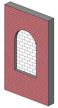
This behavior may be automatic for some curtain walls (like the storefront curtain wall). Go to the Type Properties of a Curtain Wall and you'll notice a parameter called Automatically Embed. This might be one way to model a niche.

Monday, August 28, 2006

Wall Layer Wrapping Control

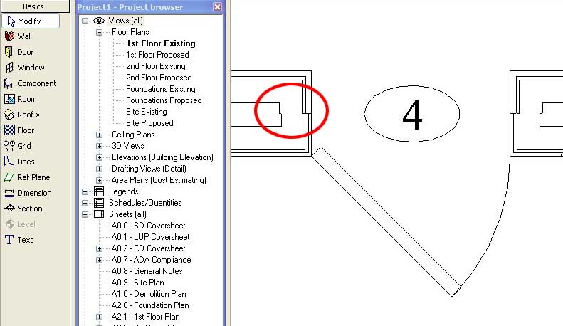
Let's say you've set your wall type parameter "Wrapping at Inserts" to Both because you want the exterior and interior finishes to wrap (as shown below).


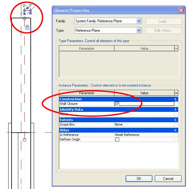
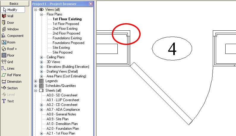
But you'll notice that by default Revit will wrap your layers to the centerline of the wall. I just discovered that you can adust where the wall wraps to. First thing you have to do is open the door (or other) family and add a reference plane (as shown below). Now select that reference plane and make sure that under its properties you change the Wall Closure parameter to TRUE. Lastly, add a dimension (like say 2 inches) and lock the dimension so that your reference plane is always 2 inches from your face of wall.


Now load your door family into a project and place it in a wall. Make sure the wall's Wrapping at Inserts parameter is set to Both. You'll notice that you can now control the location of wall layer wrapping.


You can also add a second reference plane to control exterior and interior wall layer wrapping separately.

Saturday, July 22, 2006

Stepped Foundation Plans

We often have split level projects and we've had a lot of trouble isolating the stem walls and footings from the rest of the model for use in a foundation plan... that is until Revit 9.0 came along. You can now use Revit Filters to isolate your foundation from the rest of your project.

1. Duplicate your Basic Wall: Foundation - 12" Concrete for each stem wall and footing size you need. You could use a Continuous Footing for your footings but we avoid Continuous Footings because their intersections don't clean up as nicely as Basic Walls.

2. Add the Type Comment "Foundations" for each of your new walls. Go to the wall's properties... Edit/New... Type Comments.

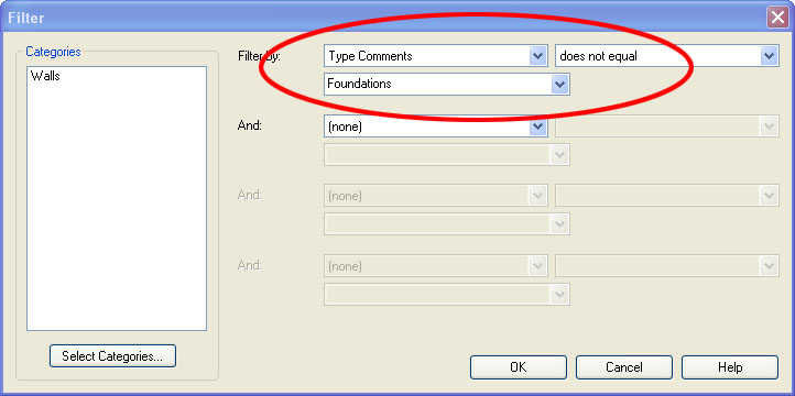
3. Set up a filter... Settings... Filters... New... call it Foundations... Check Walls... Filter by Type Comments... Does not equal... Foundations... select OK to exit.

4. Go to your foundation floor plan and type VG. Goto Filters... Insert... Foundations... and uncheck Visibility so that only walls with the Type Comment "Foundations" will show.

5. In Visibility/Graphics go to Model Categories and uncheck everything except Detail Items and Walls.

The Visibility of your view is now set to show only your stem walls, footings, and annotations. You can use the Linework tool to change your footings to dashed lines or add another Filter for Footings. You may not want to use the method described above to build your foundation plans but I thought I'd share a use for Revit's new Filter function.

You can also use phases or worksets to isolate foundations, but we prefer the filter method.

Monday, July 03, 2006

Cleaning wall intersections

Most wall intersections clean but we've had a few projects that put Revit's wall cleanup function to the test. To fix some intersections takes pushing and pulling. Here are a few tips:


  • Edit Wall Joins Tool. Sometimes all it takes is using the Edit Wall Joins Tool under Tools... Edit Wall Joins (it is also located on the toolbar above). Cycle through the various options to find one that cleans properly.

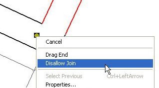
  • Disallow Wall Join. Sometimes toggling the Disallow Join function will do the trick. Select one of the walls. You'll see a blue dot indicating the end point of the wall. Right click on this dot, do a "disallow join," then back to "allow join" and the intersection may heal.

  • The "push/pull" method. If you have 3 or more walls intersecting you can try pulling them apart and reconnecting them in different orders. This pushing and pulling is about as much fun as dental work but it sometimes solves the problem.
  • Nudging a wall can sometimes fix intersections at wall openings.
  • Trim Tool. You can try pulling the walls apart and use "Trim/Extend Single Element." We've found this feature useful for cleaning up a lot of intersections that didn't clean up using the methods above. Try trimming walls in different orders until you find one that works.


  • Split Tool. If nothing else works sometimes splitting one of the walls near the intersection will allow Revit to properly connect the wall intersection.
  • Linework Tool. You can use the Linework Tool to clean up intersections but one of the above methods should do the trick.
  • Cut & Paste Aligned. Autodesk's Knowledge Base also recommends you try cutting one of the walls (Ctrl+X) and goto Edit... Paste Aligned... Same Place.
  • Edit Cut Profile. As a last resort you can use this tool to clean up connections.
  • Join Geometry can also clean some connections.

Wednesday, June 07, 2006

Edit Cut Profile Tool

Do you want a niche cut out of your wall for a soap dish or other amenity?

Draw a wall in plan view. Goto Tools... Edit Cut Profile. Select the wall in plan view. Now sketch a shape for your cut (like you would the Split Face Tool) Finish sketch and you'll notice the shape of the wall was cut. While in edit mode a blue arrow controls which side you want to keep.

This tool works in Plan, Section, and RCP views. This tool is view specific (ie. Any niche you cut out of your wall using this tool won't show in any other view.)

Thursday, June 01, 2006

Split Walls with Gap

Brian Tuffin wrote an interesting blog post on Modifying the Split Command. By editing the Revit.ini file one can add the tool "Split Walls with Gap."

This tip was also posted by Chad Smith on AUGI.

Monday, May 15, 2006

Coarse, Medium, and Fine - Wall Patterns

You might notice that wall patterns disappear when you're switching between Coarse, Medium, and Fine detail levels.

Let's say you want to show your view (plan/section) in Coarse detail level:
To edit the pattern select the wall...
go to the wall's properties... and Edit/New...
Here you can change the Coarse Scale Fill Pattern parameter.

Now let's say you've switch your view to Medium or Fine detail level:
To edit the pattern select the wall...
go to the wall's properties... and Edit/New...
edit the structure...
and select your new material...
Here you can select your new cut pattern from available fill patterns.

I'm not sure why parameters for Revit's coarse, medium, and fine detail levels cut pattern settings are separated but this is a common question so I thought I'd post the answer.