Saturday, January 13, 2007

Spot Dimensions Features

There's more to Spot Dimensions than meets the eye.

Within the Spot Dimension tool you can choose between spot elevations and spot coordinates. Spot Elevations will report the elevation of certain objects. Spot Coordinates will report the distance and direction of a point from an origin that you define (see Tools, Shared Coordinates... Specify Coordinates at a point)

While Spot Coordinates will report the coordinates of any model or drafting element it is not really clear in the help files that Spot Elevations will report the elevation of only certain parts of model elements. Here is the list of elevations that Spot Elevations will tag:

  • toposurfaces
  • roof eaves and ridges
  • stair steps and landings
  • window sills and door thresholds
  • tops of footings & beams
  • the sill and head of openings in a wall
  • any point within the area of (non-sloping) floors and ceilings
  • the height of a family's model objects (provided they are visible in the view)
  • apparently ramps too but I haven't figured this one yet
  • if you know of any more please add a comment
The visibility of Spot Elevations and Spot Coordinates can be controlled by the visibility of its host object or the visibility of the annotations themselves.

Taging the elevation of a horizontal surface won't work in wireframe mode. Spot Elevations may be deleted when trying to modify some objects in certain ways.

Two interesting parameters in the properties dialog are Relative Base and Elevation Origin. If you go to the type properties and change the Elevation Origin to Relative you will notice that the Relative Base instance parameter is no longer greyed out. You can now report the elevation of a point relative to any level you've created.

One nice thing about all Spot Dimensions is that you can control the units format separately from the project's units format by going to the type properties dialog so that their units display in decimal feet if you wish. It would be nice if levels had the same ability.

Friday, January 12, 2007

Hide & Seek (updated)

Did something in your project disappear?

  • First, check to see if it is still visible in other views.
  • Check Visibility/Graphics. Is the object category (and subcategories) ON?
  • Check Visibility/Graphics. Is the linestyle set to Override?
  • Check Visibility/Graphics. Is the detail level set to By View?
  • Check Visibility/Graphics. Are all the worksets ON?
  • Check Visibility/Graphics. Are all the filters ON?
  • Check Visibility/Graphics. If the object is in a linked file check Revit Links.
  • Check Visibility/Graphics. Check each design option.
  • Try changing phase and phase filter in View Properties (VP).
  • Try changing the detail level of the view.
  • Are all your worksets opened? (it may be hiding in a closed workset).
  • Check View Range in View Properties (VP).
  • Check for Plan Regions if in a floor plan view.
  • The object may have been moved to a new elevation.
  • Check Crop Region and Far Clip settings in View Properties (VP).
  • Set your view to wireframe. It may be hiding behind a filled region or other object.
  • Select the Linework tool (set to By Category) and see if it wasn't hidden with this tool. It would be very benefitial if one could toggle on/off the use of the linework tool in a view.
  • If the problem is with a family file open the family and check the visibility of the elements.

If you can't find it by now it was probably deleted.

Thursday, December 21, 2006

Content Highway Beta Released Today

In December 2005 Marek Brandstatter announced the development of Content Highway Desktop, a content management solution for Autodesk Revit that allows you to manage Revit family (RFA) files on your computer and optionally publish them to Content Highway Web for sharing and collaboration.

Many AUGI members were anxiously anticipating the release of this software.

Content Highway was made available today. Download the beta here.

Monday, December 11, 2006

More New Revit Blogs

ARCHIN3D by Jason G. from Boston, Massachusetts
Revit Anonymous by anonymous from Somewhere, on Planet Earth

Looking forward to reading their future posts.

Thursday, December 07, 2006

Printing visible portion of current window

I've noticed this in using Revit but wasn't aware of a solution until I read through the Bonus CD that Jim Balding passed out at AU.

If you want to print just part of a view you can go to Print... and select Visible portion of current window. The problem is that Revit doesn't usually crop the view exactly as you see it in Revit (if your project window is maximized). To crop prints more accuarately go to Window... Cascade. Now stretch your project window to the shape you want it and print visible portion of current view. Revit should crop the view more accurately. Don't forget to consider paper size and orientation.

Applications

The more accurate the information in your Revit model the more you can do with it.

Here is a list of applications mentioned and demonstrated at Autodesk University this year that utilize Revit data exported in DWG, IFC, ODBC, gbXML, and DWF formats:

Navisworks – walkthroughs, advanced collision detection, timeline analysis, supports importing data from many different applications. Models from different consultants (who use software other than Revit to model) can be combined for analysis and clash detection. Data can be shared with Primavera and Microsoft Project for project scheduling.

Project Management Software (Primavera, Microsoft Project, Constructware, Buzzsaw) – Personal dashboard for reports, scheduling, cost control, storing and sharing data files, recording correspondence, bid management, submittal package tracking, rfi tracking, and other project management functions. Designed for managers, contractors, architects. Will interface with Navisworks and Innovaya. Design Review is imbedded in Buzzsaw.

Design Review – Export Revit models into the DWF format for project managers to markup.

e-Plan Check – This program takes Revit data exported in IFC format and tests the model for building code violations. This program is not yet available for building code in the U.S.

Impression – This is very new software from Autodesk that will take DWGs exported from Revit and render illustrations in a hand-drawn style. It will apply palettes to DWG layers in plan and perspective. Similar to Piranesi.

Inventor – This software will model complex shapes that are not yet available in Revit but can be imported into Revit.

E-specs – This software will interface with Revit to construct specifications.

Success Estimator – This software from U.S. Cost will do cost estimating. Interfaces with Primavera.
Innovaya & Timberline – Also does cost estimating and will interface with Primavera and Microsoft Project. Innovaya also does visualization, communication, quantity takeoff, construction simulating, and so on.

IES & Green Building Studio – These softwares will take data from Revit in gbXML format and test for energy efficiency and LEED certification.

Revit API Examples (API is for developing applications that interact with Revit model data):

One application demonstrated a search on amazon for information describing books. The data was then fed into an application that utilizes the Revit API to assign the book name, cost, reference number, publisher name, etc to model objects in Revit which in this case happened to be books on a shelf. The application was demonstrating the future potential to populate object data from online catalogs for scheduling, spec writing, and analysis.

Another application demonstrated an alternative approach to design options. Instead of using the design options tool in Revit this application uses API to instantly swap model groups. Let's say you have 10 roof designs. Build them all and group the designs individually. The 10 options are now available in thumbnail view within the application. Using radio buttons an individual can mix and match hundreds of design iterations provided the options are all modeled and grouped.

Another application will generate custom designed reports from a template and will fill the report with any Revit data exported in ODBC format.

Monday, December 04, 2006

AU summary

Well AU was long and draining but well worth going to. I now have a better understanding of:

1. The Building Information Modelling/Management concept (its past, present, and likely future).
2. The different benefits of 3rd party applications and API plugins for analyzing, reporting, and modifying Revit data (having now seen them in action).
3. And unique modelling, documenting, and implimenting methods utilized by others in the Revit community.

I didn't do a lot of networking but I enjoyed the handful of people I met. I went to the Revit mixer but skipped a lot of the other evening events. The speakers were all very knowledgable and the event was extremely well coordinated from what I could tell. I have zero complaints.

I'll see about sharing some specifics in future posts.

Wednesday, November 22, 2006

AU2006 @ the Venetian

I'll be in Vegas all next week at Autodesk University 2006. I've got a pretty full schedule but you might find me at the Revit Mixer or the Building Industry Party. Shoot me an email if you'ld like to meet up. I'll share what I can when I get back.

Everyone have a great Thanksgiving!

Thursday, October 26, 2006

Revit Template Sharing

If you haven't already joined the AUGI Revit forum here is yet another reason to join.

Edward Borg of Precision Drafting LLC has a dedicated FTP site for sharing cool Revit Project Templates and Families. You'll also find a Revit model of Calatrava's Turning Torso project in Malmö, Sweden. See how it was modelled.


1. Join Augi
2. Login
3. Browse the Revit Template Sharing thread

FTP Details:
Host name- precisiondraftingllc.com
User name: revit
Password: 09revit!

Wednesday, October 25, 2006

Linking building and site

This is the procedure we use for linking building and site.

1. Once you have your building(s) modelled start a new project... Import your survey(dwg) into the new project and generate your toposurface from your imported instance.
2. Link your building(s) into your new site model and adjust their elevation and orientation so they are properly located in the topography. Do not relocate your topography. The topography is probably already oriented to true north and you'll want to preserve this orientation for rendering accurate sun angles.
3. Once your building(s) are located, place any building pads you need and make sure the elevations of your building(s) are where you want them. Now you're ready to share coordinates.
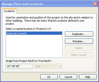
4. While in your site model goto Tools... Shared Coordinates... Publish Coordinates... and select your building(s) one at a time. This tool will share the coordinates of your site model (which is oriented correctly) with your imported building(s). Each building you select will require a named location. The default is Internal.

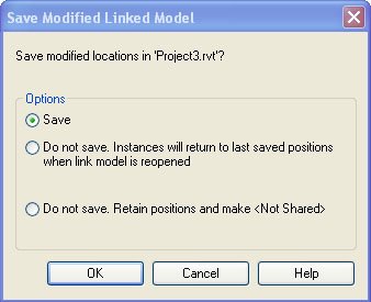
5. Save your site model. A dialog box will popup 'Save modified locations in 'Project.rvt' Go ahead and Save. You can also go to File... Manage Links... Revit... Save Locations. This procedure will open your linked model and save the new location into the linked project file but it won't affect any of your existing views in the building project file so not to worry.

6. Now that you have shared coordinates let's say you want the proper elevation to show in the levels of your building project file. While in your building project file just select a level... goto its properties... Edit/New... and change the Elevation Base parameter from Project to Shared.
7. We will often link the topography model back into the original building model for representing the topography accurately in sections and elevations. When you import the topography back into your building model make sure you Automatically Place... By Shared Coordinates. Your topography will import right where we want it to now that the two projects are sharing coordinates.

For more on Project Positioning see Steve Stafford's Revit OpEd.