Revit does not currently have a Key Plan Tool so this is what we do when we need a Key Plan on our sheets.
1. Export your Base Plan to DWG (just the unit boundaries)
2. Create a Detail Component. File... New... Family... Detail Component.rft
3. Import your Base Plan. File... Import... DWG
4. Add a Yes/No Parameter for each unit or quadrant. Family Types... Add Parameters... Type Yes/No... Set Instance Parameter... give each unit or quadrant a name.
5. Draw Filled regions for each unit or quadrant of your Base Plan and assign each one a Yes/No Parameter. To do this go to the Filled Region's properties and you'll find a Visibility check box. At the far right there is a tiny grey box. Click on it and select your new Yes/No Parameter as the parameter that defines the visiblity. Do this for each filled region.
6. Now load your new Detail Component into a Legend View in your project and set the appropriate scale.
You can now turn on and off each quadrant using the Yes/No Parameters you set up in the element's properties.
Wednesday, March 29, 2006
Tuesday, March 28, 2006
Model, Symbolic, Detail and Reference Lines
Which one do I use?
Well, when you're in the family editor you can draw symbolic lines, model lines or reference lines.
1. Symbolic lines only show in plan, elevation, or section depending on which view you're in when you draw them. Symbolic lines are typically used to "represent" door and window swings in plan and elevation.
2. Model lines will show in ALL views because they are part of the model. It's not very well documented but (while in the family editor) Detail Components placed perpendicular to a model line will "sweep" along the model line drawn (Search Augi Forums for Ultra Lightweight 3D Models to see an example). We also use model lines as a quick way to "represent detail" in some families.
3. Reference lines are essentially four intersecting reference planes. They can be used when you want to add a door swing angle parameter to your doors. Reference lines and planes should ALWAYS be used when using dimensioned parameters in a family. For more on reference lines and planes read Steve Stafford's Once Upon a Reference Plane.
When you're in the project you can draw detail lines or model lines.
1. Detail lines, like detail components, are view specific or part of the view. Anything you "draft" in a view will not show up in other views unless you copy and paste the elements into other views.
2. Model lines drawn in a project file are like those drawn in the family editor. They will show up in all views because they are part of the model.
To turn model lines into detail lines... select all model lines cut and paste into a filled region sketch. To turn detail lines into model lines... select all detail lines cut and paste into a floor sketch.
Monday, March 27, 2006
View Range
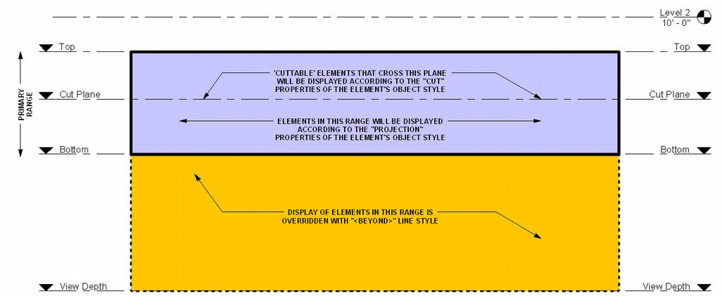
The use of View Range can be a difficult concept to grasp. The image below has been circulated around and explains how CUT, PROJECTION, and BEYOND linestyles are used by the View Range tool found in View Properties (VP) and Plan Region Properties.
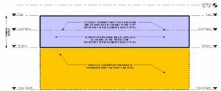
CUT and PROJECTION linestyles are controlled globally in Settings... Object Styles and for each view in Visibility/Graphic Overrides (VG). BEYOND linestyle is controlled globally in Settings... Line Styles and for each view in Visibility/Graphic Overrides (VG).
CUT and PROJECTION linestyles are controlled globally in Settings... Object Styles and for each view in Visibility/Graphic Overrides (VG). BEYOND linestyle is controlled globally in Settings... Line Styles and for each view in Visibility/Graphic Overrides (VG).
Tuesday, March 21, 2006
Floor Plan Backgrounds
Let's say you're doing your own mechanical, electrical, structural or other drawings that require a floor plan that is greyed or halftone (a background). We've found two ways to accomplish this:
Display Model As Underlay: The easiest way is to Duplicate your Proposed Floor Plan view (without Detailing) This is done by right clicking on your floor plan view in the project browser and selecting Duplicate. Now go to the View's Properties and you'll notice a Display Model parameter. By default this is set to Normal. Switch this to As Underlay. Now you can add your view specific tags, annotations, symbols, detail lines, etc. on top of the model. Unfortunately your lighting, furniture, electrical and other families will also be greyed out. If you need to show some model elements Normal then it's on to the next approach.
Visibility/Graphics Halftone: Duplicate your Proposed Floor Plan view (without Detailing) This is done by right clicking on your floor plan view in the project browser and selecting Duplicate. Now go to the view's Visibility/Graphic Overrides (VG). Under Model Categories select ALL. Now unhighlight Electrical Fixtures and Lighting Fixtures and check the Halftone box for one of the highlighted categories. Notice all the highlighted categories are now set to halftone. Click OK. You now have a floor plan background for your lighting and electrical work. Do the same for Detail Items, Electrical Equipment, Plumbing Fixtures, Furniture, Structural Framing, etc. for other disciplines. Go to View... Save as View Template... and you can save these changes to a View template for use in all your projects. To further configure View Templates go to Settings... View Templates.
To transfer View Templates and other standards from your project to a template file see Jay Polding's Importing Wall Styles.
Thursday, March 16, 2006
Revit's 16 lineweights
Revit has 16 lineweights. They say that the lineweights should be constant no matter what scale your drawing is at. We've found that's not always true. Go to Settings... Lineweights... and you'll notice that Revit has lineweights setup for 6 View scales from 1" = 1'-0" to 1/32" = 1'-0". Well what happens if you have a drawing at 1:50? Revit uses the closest thing (1/32" in this case). The good news is that you can ADD scales that Revit doesn't have setup. The bad news is you'll have to plot the 16 lineweights after you've setup your new scale and compare them with the default scales to get the settings right.
Maybe in a future release Autodesk will setup their default.rte file with the appropriate lineweights for all default scales.
Maybe in a future release Autodesk will setup their default.rte file with the appropriate lineweights for all default scales.
Wednesday, March 15, 2006
Shared Parameters
Did you add a parameter to a family but when you loaded the family into your project the new parameter won’t schedule or show up in your tags? You have to make it a Shared Parameter.
Creating the Shared Parameter File:
1. While in Revit (doesn't matter if you're in a family or project file) go to File... Shared Parameters... Create... give the txt file a name. This shared parameter file can be used on all your office's projects if you wish. Now Create Group... and add parameters you want to see in schedules or tags. The Shared Parameter file is now loaded into your Revit session for use in other family or project files.
Adding the shared parameter to your family and project files:
1. While in your family editor go to Family Types... Add Parameter... Shared Parameter... and Select your new parameter. Now while in your project file go to the schedule you want the parameter to show up in and go to View Properties... Fields... Add Parameter... Shared Parameter... and Select your new parameter.
2. If you're adding a parameter to your tags... While in your project file go to Settings... Project Parameters... Add... Shared Parameter... and Select your new parameter. Don't forget to check which family category to apply the Shared Parameter to.
If you exit all your Revit files but leave Revit running you will see that under File... Shared Parameters your shared parameters file is still loaded for use in other family or project files.
For more on Shared Parameters search Steve Stafford's RevitOpEd.
Friday, March 10, 2006
Family Visibility Control
When creating a door or other family we find that when loaded into a project we sometimes like to be able to switch on and off parts of the family but not the whole family. We have found three ways to accomplish this.
Visibility: We like to use symbolic lines to represent doors and windows in plan so we like to turn off the visibility of our model objects (glass and panel) in plan view. While in your family editor, this is simply done by selecting the object you want to hide and clicking on the Visibility button in your tool bar above. Note that this method is for turning off objects that you NEVER want to see in plan, section, elevation, or at specific Detail Levels.
Object Styles Subcategory: Another way to control the visibility of parts of a family is to setup new subcategories. While in your family editor goto Settings... Object Styles. From here you can add subcategories. Now select an object in your family and goto its properties. You'll notice that you can change the object's Subcategory. Load your new family into a project. You can now control the visibility of parts of your family GLOBALLY under Settings... Object Styles or in a SPECIFIC VIEW under View... Visibility/Graphics.
The Yes/No Parameter: While in the family editor goto Family Types... Add Parameter... And create a new Type parameter with Type (Yes/No). Now finish the Family Type and select any object in your family. Goto it's properties and you'll find a Visibility check box. At the far right there is a tiny grey box. Click on it and select your new Yes/No Parameter as the parameter that defines the visiblity. Now exit the element properties and go back into the Family Types. From here you can control the visibility of the object. Just add two new family types and uncheck the new parameter in one type while leaving it checked in the other type. The object will appear grey while in the family editor, but once you load the family into a project you will find that you can now switch on or off part of the family by switching between family types.
Wednesday, March 08, 2006
Naming Conventions
If you're responsible for establishing a naming convention for your Project Files you're probably wondering what other offices do. This is what we've established.
Project files: [project number] [project name] - [Central or User] - [version]
Example: 0513.00 Johnson - Central - 03.rvt
Family files: [office initials] [family category] - [title] - [version] - [project precedent]
Example: AA Window - Dbl4x4 - 01 - Garden Lane.rfa
Group files: [office initials] [group category] - [title] - [version] - [project precedent]
Example: AA Door - Dutch Door - 02 - Hope.rvg
1. We name our files from general to specific so that when they sort in windows explorer finding what you want is easier.
2. Office Initials are reserved for files that are established standards. If it doesn't have our initials it isn't a standard yet.
3. Version numbers are necessary because we often have many versions of the same thing.
Tuesday, March 07, 2006
Dimension Text Override
To override or not to override... Which camp are you in?
Maybe you've noticed that you cannot override dimension text like you would in AutoCAD. You can however add a Prefix and Suffix to dimensions under the dimension's Properties. If you absolutely must override dimension text (for Verify In Field or other common notes) here is what we've done:
1. Select the dimensions tool and goto its properties.
2. Click on Edit/New.
3. Click on Duplicate to create a new Dimension Type.
4. Give the dimension type a new name like... Blank
5. Now Change the text size to 1/256" (smallest you can get)
6. Change Units Format to Decimal Feet and rounding to 0 decimal places. You now have a font that is so small it won't register.
7. Now just use the Text tool to add whatever text you need on top of your "blank" dimension.
Thursday, March 02, 2006
Phases & Phase Filters
Are you doing a remodel project? You’ll need to learn about phases. There are 3 dialog boxes you’ll have to become more familiar with.
1. Phase Settings: Under Settings... Phases... you will find Project Phases, Phase Filters, and Graphic Overrides.
Project Phases: Here you can add new phases to the project. The best practice is to set these up before you begin work on your project. Later Phases are ok to add at a later date but you cannot rearrange the order of phases after entering them. Revit is setup by default with Existing and New Construction phases.
Phase Filters: Here you can control the graphics used for objects who’s relative phases are set to New, Existing, Demolished, or Temporary. Phase Filters will determine whether the Category’s Object Styles are used or whether Revit will use the Graphic Overrides established under the Graphic Overrides tab. You should leave these alone until you grasp an understanding of them.
2. View Properties: Every View has View Properties (VP). In the view properties you will find the Phase and Phase Filter used for that particular view. It is very important that you setup duplicate views for each phase (Existing and New Construction).
Phase: Revit’s views are setup by default with the New Construction Phase. This simply means that all objects placed in this view will automatically be set to New Construction and will show. If you plan on using a remodel project to learn Revit (or teach someone Revit) make sure you setup all the view's phases to Existing before you start. This way you don’t have to think about what phase you’re placing an object in and you won’t have to switch all of the objects from New Construction to Existing after the model has progressed. Once you’re ready to move on to the addition then you can add new views and set their phases to New Construction.
Phase Filter: Revit’s views are setup by default with Show All phase filter. We typically change this to Show Complete. The chosen phase filter will determine how objects that are New, Existing, Demolished, or Temporary (relative to the active phase) will display. Goto Settings... Phases... Phase Filters to view and modify how phase filters affect the display of objects.
3. Object Properties: Under the properties of most objects you will find Phase Created and Phase Demolished.
Phase Created: In what phase was the object created? For example, when you place an object into a view that is set to the Existing Phase the object's properties will automatically reflect that the object was created in the Existing Phase. If the view’s phase is set to Existing and you change the object’s Phase Created to New Construction the object is still there but will disappear from view because the view is setup to only show objects placed in the Existing Phase.
Phase Demolished: In what phase was the object demolished? Very simply if you demolish an Existing object in the New Construction phase the object will display as dashed lines in views who’s phases are set to New Construction. However, the object will still display as whole in views who’s phases are set to Existing.
Wednesday, March 01, 2006
Revit Resources
Did you buy a revit subscription? You should have access to 100 class sessions recorded at AU 2005 in Orlando. Just login to the Autodesk Subscription Center and click on AU Online 2005. You might have to reset your password with Autodesk if you don't remember it... it's worth it. Other great tutorials are available at DGCAD. If you're having a problem you can't solve you can also file a support request with AutoDesk. Go to Help... Create Support Request. They usually respond within 2 hours. Their support is excellent.
Are you looking for Revit Families online? Go to File... Load from Library... Load Family... and click on Web Library or you can try Symbol Machine and RevitCity's Family Explorer.
Want to ask other Revit users how to accomplish something? Signup for forums at AUGI and RevitCity.
Are you looking for material textures online? Goto Google and type... download textures. http://astronomy.swin.edu.au/~pbourke/texture/
You found this blog so I assume you can find many of the other blogs that are available online. Feel free to comment on your favorite resources.
Subscribe to:
Posts (Atom)