Do you want to know if Text Backgrounds used in a view are opaque or transparent?
Are you trying to find hidden filled regions in a view?
Are you having trouble distinguishing detail lines from model lines in a view?
Well, the easiest way to separate view specific content from model content in a view is to place a temporary filled region with a Solid Fill Pattern that covers the entire view (choose a neutral color). Then just select the filled region and Send To Back. All view specific content will pop out and all model content will be hidden behind your Filled Region.
However, if you want to know where the Linework Tool was used you'll have to resort to selecting the Linework Tool... By Category... and floating your mouse over the model to "scan" for where it may have been used. Lines will highlight when you roll your mouse over them if the Linework Tool was infact used.
Showing posts with label Lines. Show all posts
Showing posts with label Lines. Show all posts
Monday, March 05, 2007
Monday, September 11, 2006
Utility Lines Workaround
In AutoCAD you can add text to linetypes but you'll notice that in Revit you can't... unless you use this workaround. This workaround involves drawing a repeating detail line (with imported text) on top of a simple detail line.
1. Type out the text you want in AutoCAD (at a height of say 6") and save as a DWG.
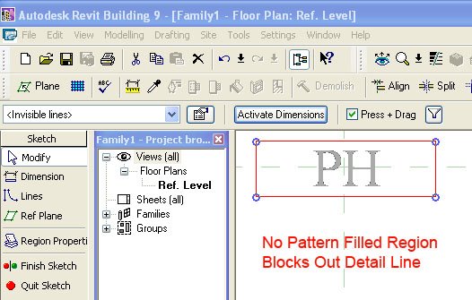
2. Goto File... New... Family... Detail Component and import your DWG into your new Detail Component.
3. Place a masking region behind your imported text (as shown).
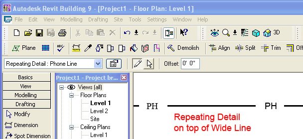
5. Goto Drafting... Repeating Detail... Properties... Edit/New... Duplicate... and give your repeating detail a name (phone line as an example). Set Detail Rotation to "90° Counterclockwise" and spacing to something like 10'.
6. Now draw a detail line in any view of your project. Draw your repeating detail over your new detail line as though tracing the detail line.
1. Type out the text you want in AutoCAD (at a height of say 6") and save as a DWG.
2. Goto File... New... Family... Detail Component and import your DWG into your new Detail Component.
3. Place a masking region behind your imported text (as shown).
5. Goto Drafting... Repeating Detail... Properties... Edit/New... Duplicate... and give your repeating detail a name (phone line as an example). Set Detail Rotation to "90° Counterclockwise" and spacing to something like 10'.
6. Now draw a detail line in any view of your project. Draw your repeating detail over your new detail line as though tracing the detail line.

Combining repeating details and detail lines you now have a workaround for creating utility lines for gas, elec, phone, sewer, storm drain, etc. Daphne (one of our staff) suggested trying this.
Tuesday, March 28, 2006
Model, Symbolic, Detail and Reference Lines
Which one do I use?
Well, when you're in the family editor you can draw symbolic lines, model lines or reference lines.
1. Symbolic lines only show in plan, elevation, or section depending on which view you're in when you draw them. Symbolic lines are typically used to "represent" door and window swings in plan and elevation.
2. Model lines will show in ALL views because they are part of the model. It's not very well documented but (while in the family editor) Detail Components placed perpendicular to a model line will "sweep" along the model line drawn (Search Augi Forums for Ultra Lightweight 3D Models to see an example). We also use model lines as a quick way to "represent detail" in some families.
3. Reference lines are essentially four intersecting reference planes. They can be used when you want to add a door swing angle parameter to your doors. Reference lines and planes should ALWAYS be used when using dimensioned parameters in a family. For more on reference lines and planes read Steve Stafford's Once Upon a Reference Plane.
When you're in the project you can draw detail lines or model lines.
1. Detail lines, like detail components, are view specific or part of the view. Anything you "draft" in a view will not show up in other views unless you copy and paste the elements into other views.
2. Model lines drawn in a project file are like those drawn in the family editor. They will show up in all views because they are part of the model.
To turn model lines into detail lines... select all model lines cut and paste into a filled region sketch. To turn detail lines into model lines... select all detail lines cut and paste into a floor sketch.
Thursday, March 16, 2006
Revit's 16 lineweights
Revit has 16 lineweights. They say that the lineweights should be constant no matter what scale your drawing is at. We've found that's not always true. Go to Settings... Lineweights... and you'll notice that Revit has lineweights setup for 6 View scales from 1" = 1'-0" to 1/32" = 1'-0". Well what happens if you have a drawing at 1:50? Revit uses the closest thing (1/32" in this case). The good news is that you can ADD scales that Revit doesn't have setup. The bad news is you'll have to plot the 16 lineweights after you've setup your new scale and compare them with the default scales to get the settings right.
Maybe in a future release Autodesk will setup their default.rte file with the appropriate lineweights for all default scales.
Maybe in a future release Autodesk will setup their default.rte file with the appropriate lineweights for all default scales.
Monday, January 30, 2006
Changing Line Styles
There are a number of ways to change linestyles and it is important to be familiar with all of them. It took me some time to track down how to change different linestyles so I thought I'd dedicate a post to linestyles.
Linestyles for Model Objects like walls, doors, roofs, topography and other families are located under Settings... Object Styles. Here you can set the Color, Pattern, and Material of any family's linestyle. You can also change the lineweight of the family's Cut and Projection lines. Cut lines are lines that your plans and sections are cutting through. Projection lines are lines BEYOND or lines that lie beyond the cutting plane. You will also find linestyles for Annotations and Imported Objects here. These changes will affect linestyles GLOBALLY. If you want to change a linestyle in just one particular view you will have to go to View... Visibility/Graphics or use the Linework Tool.
Let's say you're drafting with Model Lines and Detail Lines. At the moment these linestyles are located under Settings... Line styles... but there is talk of moving them in with the Object Styles.
Now let's say that you've started a new family using one of the family templates but you can't find the linestyle that you want (say a dashed line for instance). To create a new linestyle go to Settings... Objects Styles... and add a Subcategory. Construct your family and import it into your project. You now have the power to turn on/off your new linestyle under View... Visibility/Graphics.
Now let's say you've constructed a model of your project but there are stray lines that you can't seem to get rid of. You can use the Linework Tool (LW) to set any visible line... invisible. Another great use for the Linework Tool is if you wanted to show the line of a balcony above in your plan view. Goto the view's properties and change the Underlay from None to 2nd Floor for instance. Now use the linework tool on the edge of the balcony above and turn off the underlay. You'll notice that the new linework remains. The linework tool is view specific so any changes you make are only going to be visible in the current view.
Now let's say you just want to OVERRIDE the linework in one specific view. For this we go to View... Visibility/Graphics (or VG for short). Here you can override Line Weight, Line Color, Line Pattern and we can Halftone an entire or part of any category. Halftone comes in handy when you've imported a DWG that you want to show in greyscale.
Drafting and model patterns use lineweight 1 end of story. If you want patterns with heavier lineweights you'll have to use filled regions.
Now lets say you have a floor, wall, or ceiling with many layers in their construction (finish, sheathing, framing, etc) and you want to change the lineweight, color, or pattern of one of the layers. If you go to View... Visibility/Graphics... and check the Cut Line Styles box you can now edit Host Layer Line Styles.
I think that pretty much covers linestyles for this post and I hope you've found it helpful.
Subscribe to:
Posts (Atom)