Friday, September 29, 2006

2D vs 3D Datum

You might notice that when you move the endpoint of a gridline in plan A it moves in plan B as well. Same goes for Reference Planes and Levels. Select a datum and it is selected in all views in which it is visible. You'll notice a blue icon that reads 3D. Click once on the icon and it switches to 2D mode. The datum is now view specific and free to move in this view independent from the same datum in other similar views.
Applying a crop region or scope box to a view can also affect the location of your datum extents.

To set a datum to 2D mode in all views select the datum, change it's mode to 2D and click on the Propagate Extents button in the options bar. The datum choosen is now free to move independently in all similar views.

Embedded Walls

Walls can be embedded into other walls using the Cut Geometry command. Overlap two walls of different types... Select the Cut Geometery Tool... and click on the two walls (host wall first).

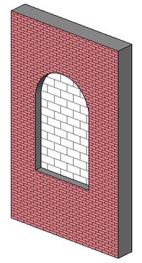
This behavior may be automatic for some curtain walls (like the storefront curtain wall). Go to the Type Properties of a Curtain Wall and you'll notice a parameter called Automatically Embed. This might be one way to model a niche.

Wednesday, September 27, 2006

Freedom Tower Webcast

For those of you interested in seeing how structural and mechanical engineers are collaborating in Revit to design the Freedom Tower there is a webcast Thursday, October 5, 2006 from 9:00 – 10:00 a.m. (PDT)

Surveys and Site Plans

We quite often import survey data into Revit from DWG files given to us by the surveyor. Here are a few tips to consider when importing (and exporting) surveys.

1. Under File... Import/Link... CAD Formats... If you check "Link (instead of import)" you're keeping the project file size smaller. If you want to import the survey later you can always Import under File... Manage Links.

2. If you check "Current view only" your survey will only show in the active view (similar to detail lines). If you uncheck "Current view only" your survey will be visible in all of your views... elevations, sections, 3D views, etc (similar to model lines) and you'll have to adjust its visibility one view at a time.

3. Now let's say you've developed your site plan (with linked survey) and you want to export the data (including survey) back to DWG format. If you go to File... Manage Links... and Import your linked survey then it will export with the rest of your model to DWG format. If you don't Import your survey you'll notice that only revit components will export. The survey needs to be a part of the Revit model or Revit won't consider it when exporting your site plan to DWG.

UPDATE (09/27/06):
In Revit Building 9.1, when a DWG or DXF survey file is imported with the Current View Only checkbox checked, you cannot select the DWG/DXF instance to create a terrain model from the instance like you could with 9.0 and earlier versions. So imported data to be used for creating a toposurface must be imported with the Current View Only checkbox cleared. Thanks to Wes Macaulay on AUGI for posting this issue. Doesn't look like Autodesk is going to change this behavior.

Tuesday, September 26, 2006

Ductwork and Flues

Found an interesting feature in sweeps today. Create a sweep with an arched path. Go to the sweeps properties and you'll notice two parameters (Trajectory Segmentation & Maximum Segment Angle). Set the Trajectory Segmentation to true and choose a maximum segment angle. You now have yourself ducts and flues in Revit Building.

AU Connect now online

AU Connect is now online for those of you going to Autodesk University. Yes, I'm going this year. This will be my first year.

Monday, September 25, 2006

Modifying the Date Stamp

Sometimes users ask if the date stamp that appears on plots can be modified.

1. Select your titleblock... Edit Family... and you can change the font, size, visibility, and location of your date stamp.
2. What some beginners don't know is that you can also go to Regional and Language Options in Windows' Control Panel and customize the date and time formats.
3. If you still can't get the exact formating you want you can opt not to use the Date/Time Stamp parameter and create a new shared parameter of your own.

Friday, September 22, 2006

Loading Libraries

Goto File... Load from Library... Load Family and you'll notice icons on the left for Desktop, My Documents, My Computer, My Network Places, Imperial Library, Imperial Detail Library, and Training Files. Many beginners don't know that one can add to and customize this list of icons. Just goto Settings... Options... File Locations and add as many Libraries as you like.

To make loading families faster add a hotkey (like FF for Family Files) to the keyboardShortcuts.txt file:

"FF" menu:"File-Load from Library-Load Family"

NOTE: This tip can also be used for quickly loading project files. Go to File... Open and you'll see the same icons so you can add all your project directories too.

Wednesday, September 20, 2006

Family Templates

Let's say you have an office standard for how doors and windows should appear in plan view and you want to incorporate this or any other standard as part of your door and window templates. Here are a few things you should know:

1. Save your templates under a new name so users still have access to the door and window templates that ship with Revit.
2. To edit a template change it's file extention from .rft to .rfa.
3. Anything you place in the template can not be deleted once you open the template as a new family file (File... New... Family) so don't try to create new templates this way. Instead you should create new templates by changing an existing template file extention from .rft to .rfa and saving the template under a new name.

Monday, September 18, 2006

Two New Bloggers

Troy Gates of Costa Mesa is an Application Engineer for L.A. CAD with a new blog called Revit Coaster. I look forward to reading his future posts.

J B Zallan of Los Angeles is a Revit, Architectural Desktop, AutoCAD consultant and Autodesk Approved Instructor who's sharing his thoughts at CAD vs BIM... A junkies guide to overcoming addictions to lines.

Check out the new SpacePilot (and to think I was just joking with the guys at work the other day when I said that all Revit needs now is a joystick).

Tuesday, September 12, 2006

Head & Sill Height Behavior

Did you model a rough opening height for your window that has say a sloping sill and now your head height is not accurate in your schedule? This is why.

We've recently discovered that the Head Height instance parameter in a door or window family is calculated from Sill Height + Height (easy right? wrong). It's not the Default Sill Height parameter as you would expect but rather the lowest point of your geometry that defines the Sill Height Revit uses to calculate Head Height (Head Height = 2'-8" + 4'-0" but should be 3'-0" + 4'-0") .

Raise or lower the lowest point of your door or window opening 4 inches and load it into your project file. Everything may look fine until you go to the window's properties and notice the head and sill height are just plain wrong. They will also schedule wrong unless you do the following.

To resolve this set the Defines Origin parameter for the Sill reference plane to TRUE. (red flag: be sure and check head and sill heights in your window schedule before plotting if you do decide to use these parameters). Thanks to Steve Stafford for resolving this issue.

Monday, September 11, 2006

Utility Lines Workaround

In AutoCAD you can add text to linetypes but you'll notice that in Revit you can't... unless you use this workaround. This workaround involves drawing a repeating detail line (with imported text) on top of a simple detail line.

1. Type out the text you want in AutoCAD (at a height of say 6") and save as a DWG.
2. Goto File... New... Family... Detail Component and import your DWG into your new Detail Component.
3. Place a masking region behind your imported text (as shown).

4. Load this Detail Component into your project.
5. Goto Drafting... Repeating Detail... Properties... Edit/New... Duplicate... and give your repeating detail a name (phone line as an example). Set Detail Rotation to "90° Counterclockwise" and spacing to something like 10'.
6. Now draw a detail line in any view of your project. Draw your repeating detail over your new detail line as though tracing the detail line.

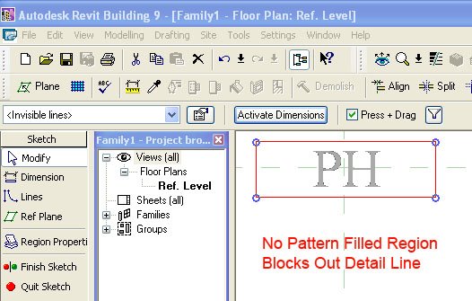
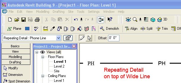
Combining repeating details and detail lines you now have a workaround for creating utility lines for gas, elec, phone, sewer, storm drain, etc. Daphne (one of our staff) suggested trying this.