I'll give you a basic intro to worksets and provide a few tips we've learned.
When you have a large project and you want multiple users editing a project at the same time you have to implement Worksets because Revit typically keeps all project data in a single project file unlike Autocad where we typically separate the project into multiple files.
Go to File... Worksets... to activate the Worksets feature in your project file. Revit will by default divide the project into 2 worksets "Shared Levels and Grids" and "Workset 1." All of your model objects will initially reside in Workset 1. You can further divide Workset 1 into other user-created worksets at some future time.
Save your new project file to a central server where everyone can access it. The file you're working in is now the Central File. Before making any more changes to the project file go to File... Save As... and save a local copy of this central file to your desktop (each user should save a local copy onto their desktop before they start working on a project file). You now have a Central File on the server and a duplicate Local file that you will be working in. If you ever wanted to make your Local copy a Central File goto Options when you Save As and check the box to "Make this the Central location after save."
Now from your local copy go to File... Worksets (there is also a worksets toolbar available). When a workset is opened it is loaded into memory and visible in all views. If you find the project is too slow with all the worksets opened then just close the worksets you won't be working on, but remember to open all the worksets again before plotting.
When you make a workset Editable you are the sole owner of a workset. You are the only person who can edit the workset.
When you select an object that's in a Non Editable workset you'll see a blue puzzle icon. Click on the icon and Revit will let you Borrow the element provided there are no users who Own the workset you're borrowing from.
You can rename and edit worksets that are User-Created. The three other workset types View Worksets, Family Worksets, and Project Standards are automated worksets that you can only turn on/off.
Here are a few tips we've learned in implimenting Worksets:
1. Enable worksets when you expect to have multiple users accessing the project file at the same time or when you expect the project is going to get so big that keeping the whole project open is going to be a strain on your workstations resources.
2. If you're going to open and close worksets for increased speed it is best to initiate the worksets feature as soon as possible. If you don’t initiate worksets early on you’re going to have to assign every model object to a workset after they’ve already been created and that can be a lot of unnecessary work.
3. If you are just going to use worksets so multiple users can access one file then the worksets feature can be enabled at any time. I would advise against adding more than the (2) default worksets unless the project file is just too slow and you're willing to spend half your time managing objects and the worksets they reside on.
4. When ever possible BORROW elements instead of OWNING worksets. We find that no matter how you divide your worksets users inevitably need to work on different parts of the same workset.
5. If you can help it do not use worksets to control visibility of objects in a view. Worksets are for closing large parts of the model when loading them is a strain on the resources of your workstation and for making project files accessible to multiple users.
There is a lot more to know about worksets but hopefully this gives you a place to start.
EDIT (4/18/2014): This post was, and continues to be, the most popular post on my blog so I thought I'd add a few additional tips.
6. If you have a site model with 10 buildings linked into it, consider putting each linked file on its own workset. When I'm working on a site model I always open "by selective worksets" to open just Workset 1, Shared Levels and Grids, and perhaps one of the buildings I'm modeling sitework around.
7. Keep in mind that when putting a linked model on a workset it has a setting for the workset in both instance and type parameters. Might be a good thing to know before you start.
8. There was a question about enabling worksets in a project template. Revit does not support worksets in template files BUT you can do all of your template work in a workshared project file (say if you've assigned multiple authors to one template), then make that project file a template file (detach and discard worksets) when you are ready to publish the template. More on AUGI
9. Never delete all the worksets (yes it has happened). You have to detach without preserving worksets and recreate a central with the "restored and default" worksets.
10. You can Own a workset with a special character username to lock everyone out of it (to prevent tip #9 for example).
11. Hint: If you are having performance issues consider that Local and central files are usually not the same size. Compacting one or the other or both are all options.
Tuesday, June 27, 2006
Tuesday, June 20, 2006
Section Annotation Features
There's more to Sections than meets the eye.
1. Goto the View... Section. You'll notice that you can select between a Building Section, Wall Section, and Detail View. Select the Detail View. In the options bar you'll notice that you can "Reference other view" (for referencing a drafting view that is already present). Place a Detail Section. Now goto View... Callout and place a Detail Callout. You'll notice that graphically they look different but they serve the same purpose and function in much the same way. Beginners often overlook that one has the choice between these two Detail Annotation styles.
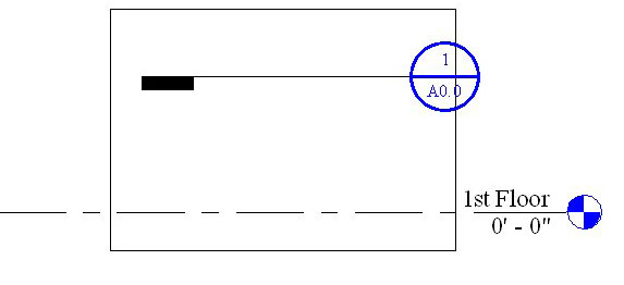
2. Place a building section line and select it. You'll notice two blue circular arrows show up at either end of the section line. Click on it to cycle through section tail types. You'll also notice a blue breakline in the center of the section. Click on it to break the section into segments.
3. Place a building section line and select it. In the options bar you can "Split Segment." Place your cursor anywhere on the section line and start splitting the section line into segments.
4. Sometimes section lines disappear. Right click on the section and you can "Hide annotation in view." Goto the sections properties and you'll notice the parameter "Hide at scales coarser than." If your view is at a scale coarser than the parameter shown then the section annotation will disappear.
5. You can goto Settings... View tags... Section tags... to change the look of building, wall, and detail section annotations. Goto Settings.. View tags... Callout tags... to change the look of detail callouts. You can only choose from loaded Section and Callout Head annotation symbols. Edit those families for more custom heads.
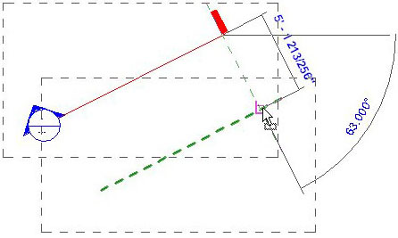
Now a common problem is how do I get a section line EXACTLY where I want it?
Let's say you wanted a section at a very specific angle and at a very specific place in plan view that is not orthogonal. Just draw a reference plane at the angle you want (and in the location you want for your section line) then place your section line adjacent to the reference plane. The section line will snap to the angle of an adjacent reference plane but won't snap to the reference plane itself. Now, to align your section line with the reference plane the align tool isn't going to work. So, select the move tool, hover over the section tail (revit will snap to the section line), and just move the section from it's present location to the reference plane.
1. Goto the View... Section. You'll notice that you can select between a Building Section, Wall Section, and Detail View. Select the Detail View. In the options bar you'll notice that you can "Reference other view" (for referencing a drafting view that is already present). Place a Detail Section. Now goto View... Callout and place a Detail Callout. You'll notice that graphically they look different but they serve the same purpose and function in much the same way. Beginners often overlook that one has the choice between these two Detail Annotation styles.
2. Place a building section line and select it. You'll notice two blue circular arrows show up at either end of the section line. Click on it to cycle through section tail types. You'll also notice a blue breakline in the center of the section. Click on it to break the section into segments.
3. Place a building section line and select it. In the options bar you can "Split Segment." Place your cursor anywhere on the section line and start splitting the section line into segments.
4. Sometimes section lines disappear. Right click on the section and you can "Hide annotation in view." Goto the sections properties and you'll notice the parameter "Hide at scales coarser than." If your view is at a scale coarser than the parameter shown then the section annotation will disappear.
5. You can goto Settings... View tags... Section tags... to change the look of building, wall, and detail section annotations. Goto Settings.. View tags... Callout tags... to change the look of detail callouts. You can only choose from loaded Section and Callout Head annotation symbols. Edit those families for more custom heads.
Now a common problem is how do I get a section line EXACTLY where I want it?
Let's say you wanted a section at a very specific angle and at a very specific place in plan view that is not orthogonal. Just draw a reference plane at the angle you want (and in the location you want for your section line) then place your section line adjacent to the reference plane. The section line will snap to the angle of an adjacent reference plane but won't snap to the reference plane itself. Now, to align your section line with the reference plane the align tool isn't going to work. So, select the move tool, hover over the section tail (revit will snap to the section line), and just move the section from it's present location to the reference plane.
One last thing. If you don't like the look of Revit's Elevation tag you could design your own section head (for use as an elevation tag) and use these modified sections instead of the given elevation tags.
Monday, June 19, 2006
Callout Annotation Features
Goto View... Callout. You'll notice you can select a Floor Plan or Detail View callout. Select Detail View and draw a callout in plan view. Select the callout and goto its properties. You'll notice the parameter "Show in" is set to "Parent view only". Change it to "Intersecting views." Now place a building section in plan view that intersects the callout region.

Tuesday, June 13, 2006
More Revit Content
Form Fonts is a new subscription service offering Revit content.
Revit Drop is another subscription service with some free content.
CadPlan has content if you don't mind that it's in metric.
SaleSoft has a content library also in metric.
Revit Drop is another subscription service with some free content.
CadPlan has content if you don't mind that it's in metric.
SaleSoft has a content library also in metric.
Friday, June 09, 2006
Sort by Submittal Package
Quite often we need to organize our plots for different submittal package sets (Schematic Design Presentation, Land Use Permit, Plan Check, Construction Admin, etc). Revit has the built-in ability to do this. Just goto File... Print... Selected views/sheets... Select... Here you can check off the sheets you want to plot and you can save those changes for different submittal packages. Unfortunately, there's not much you can do about any annotation references that cross over between submittal packages.
We decided that we also wanted to be able to sort the sheets in our project browser (and our drawing lists) by Submittal Package. It's possible but it's not an easy thing to do.
First, go to Settings... Project Parameters... Add. Now type in the Name "Submit for SD"... select the Yes/No Parameter... and check the category Drawing Sheets.
Now goto Settings... Browser Organization... Sheets... New. Call your new Browser Tree "Submit for SD". Goto the Filter tab... Filter by Submit for SD... Equal To... Yes. Now exit the Browser Organizer (while saving changes), right click on Sheets (all) in your project browser, and click on Properties. You'll notice your new Browser Tree "Submit for SD" is in the Type drop down list. Select the "Submit for SD" option.
Now goto View... New.. Drawing List... and add ALL the parameters (including Submit for SD). Leave the name Drawing List. If you look at your new schedule you'll notice that under the column Submit for SD you can check which sheets you want to apply to your Schematic Design Submittal Package. If the check boxes are greyed out just select them one at a time to active them. You might also notice that as you check and uncheck different sheets that your list of sheets in the project browser changes too.

Now that we can sort our project browser by Submittal Package we have a new problem. The Drawing List on our coversheet shows ALL the drawings from ALL the different packages. We're going to need a different Drawing List for each submittal package. You'll probably want different Coversheets for each submittal package too so set up a coversheet for each of your submittal packages starting with an SD coversheet.
Goto View... New.. Drawing List... and add the parameters: Submit for SD, Sheet Number, and Sheet Name. Click on the Formatting tab and select Submit for SD. Make this parameter a Hidden Field. Click on the Filter Tab and Filter by Submit for SD... equals... YES. Select OK and rename this drawing list "Drawing List - SD". Now you can do the same for each of your submittal packages (LUP for Land Use Permit, ConDocs for construction documents, etc). Drag each of your new Drawing Lists into their respective coversheets.
Now if Autodesk would add the Print Set parameter to Drawing Lists fields then we could coordinate the sheet browser, drawing list, AND the Print Range settings.
Wednesday, June 07, 2006
Edit Cut Profile Tool
Do you want a niche cut out of your wall for a soap dish or other amenity?
Draw a wall in plan view. Goto Tools... Edit Cut Profile. Select the wall in plan view. Now sketch a shape for your cut (like you would the Split Face Tool) Finish sketch and you'll notice the shape of the wall was cut. While in edit mode a blue arrow controls which side you want to keep.
This tool works in Plan, Section, and RCP views. This tool is view specific (ie. Any niche you cut out of your wall using this tool won't show in any other view.)
Thursday, June 01, 2006
Split Walls with Gap
Brian Tuffin wrote an interesting blog post on Modifying the Split Command. By editing the Revit.ini file one can add the tool "Split Walls with Gap."
This tip was also posted by Chad Smith on AUGI.
This tip was also posted by Chad Smith on AUGI.
Subscribe to:
Posts (Atom)