Sunday, July 23, 2006

Rafters on Top Plate

If you've sketched your roof using Lines in the Roof By Footprint mode you'll notice that your roof may not be resting on your top plate the way you would expect it to.

Instead of adjusting the elevation of your roof manually... sketch your roof using Pick Walls instead. The roof will now rest on your top plate (Level 2).

But by default Revit will treat your roof joists as trusses. To get your rafter resting precisely on your top plate you will have to go into the roof's properties and change the "Rafter or Truss" parameter to Rafter. This parameter will not be available if you've sketched your roof using Lines.

Understanding how Revit places a roof in section can be difficult if you're not aware of this Revit behavior.

UPDATE (12/05/06):
Don't mix pick lines and pick walls in the same roof sketch or you'll experience ill formed roofs.

Saturday, July 22, 2006

Stepped Foundation Plans

We often have split level projects and we've had a lot of trouble isolating the stem walls and footings from the rest of the model for use in a foundation plan... that is until Revit 9.0 came along. You can now use Revit Filters to isolate your foundation from the rest of your project.

1. Duplicate your Basic Wall: Foundation - 12" Concrete for each stem wall and footing size you need. You could use a Continuous Footing for your footings but we avoid Continuous Footings because their intersections don't clean up as nicely as Basic Walls.

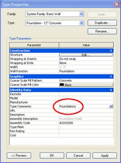
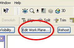
2. Add the Type Comment "Foundations" for each of your new walls. Go to the wall's properties... Edit/New... Type Comments.

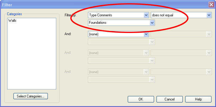
3. Set up a filter... Settings... Filters... New... call it Foundations... Check Walls... Filter by Type Comments... Does not equal... Foundations... select OK to exit.

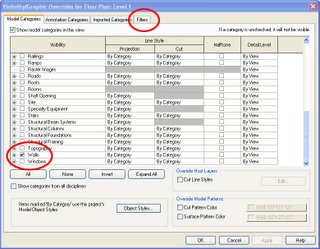
4. Go to your foundation floor plan and type VG. Goto Filters... Insert... Foundations... and uncheck Visibility so that only walls with the Type Comment "Foundations" will show.

5. In Visibility/Graphics go to Model Categories and uncheck everything except Detail Items and Walls.

The Visibility of your view is now set to show only your stem walls, footings, and annotations. You can use the Linework tool to change your footings to dashed lines or add another Filter for Footings. You may not want to use the method described above to build your foundation plans but I thought I'd share a use for Revit's new Filter function.

You can also use phases or worksets to isolate foundations, but we prefer the filter method.

Friday, July 21, 2006

Multiple Project Orientations

Lets say you have three buildings on your site and they are all at different angles. If you go to View Properties you'll notice that for orientation you only have a choice between Project North and True North, but what if you need to work in plan views that are orthagonal to each building?

Just setup duplicate floor plan views for each building and turn on your crop regions. Select the crop region and you can rotate the view to any angle you need. Because you've created duplicate views you can now preserve the different angles in each view for all time. Keep in mind, Revit will rotate your view in the opposite direction that you rotate your crop region.

Thursday, July 20, 2006

IFC/ODBC Software

I'm exploring Cost Estimating, Facilities Management, Specification Writers, and Material Takeoff softwares that utilize IFC and ODBC data that can be exported from Revit. I've added links to some of these softwares on my blog. Please feel free to comment if you have any experience using IFC or ODBC data exported from Revit.

Wednesday, July 19, 2006

Parametric Column Families

Have you tried everything and you can't get your column to stretch parametrically?

It can be a difficult task to figure out. There is no way to scale a column globally so that the proportions of your beautiful column are preserved (wishlist item alert) but we can show you how to build simpler columns that stretch properly.

The example below is an adjustable column with adjustable base.

First thing you need to setup are reference planes. We have the given Ref Level and we've created a Top of Base and Top of Capital. Remember to goto the plane's properties and give each plane a unique name (we will use this later). Dimension these planes and attach your parameters (as shown below).

Second you have to create each of your elements for base and capital. Now the trick is that after you've created your elements you have to Edit the work plane of each element so that the elements are attached to the reference plane you would like them to "travel with." when adjusting the height parameters.


In this example we've attached our elements to Ref Level, Top of Base, and Top of Capital (as shown below).

Now load your column into a project and place it on the 1st and 2nd floors to make sure that the elements are correctly placed and stretch properly in both scenarios.

Tuesday, July 11, 2006

View Range & Visibility Lessons

We ran into two interesting View Range problems today.

Interior elevation tags from the first floor plan were mysteriously showing up on the second floor plan. That's because if the top of the crop region for an interior elevation view intersects the primary range (bottom clip plane) of the floor plan above, then the interior elevation symbol will show in the floor plan above. So you have to either lower the top of the interior elevation's crop region or you have to raise the bottom clip plane of the primary range in the floor plan above. Thanks to Steve Valenta on AUGI for pinpointing the exact solution.

While in the second floor plan we underlayed the 1st floor plan but the 1st floor plan walls were not visible while doors, windows, and fixtures were. That's because if the top of the wall below intersects the primary range (bottom clip plane) of the floor plan above, then Revit won't include the walls in the underlay. So we had to raise the bottom clip plane which shouldn't have been below the floor level anyway.

Monday, July 10, 2006

Free Revit User Guide

Three resources I've recently learned of:

1. If you bought a seat of Revit you should be able to get a 708 page Revit User Guide free of charge. Just type in your part number and serial number here. Posted by Damian on AUGI.

2. You can find resolutions to many common problems at Autodesk's Support Knowledge Base.

3. You can also send your wishlist directly to Autodesk here.

Monday, July 03, 2006

Cleaning wall intersections

Most wall intersections clean but we've had a few projects that put Revit's wall cleanup function to the test. To fix some intersections takes pushing and pulling. Here are a few tips:


  • Edit Wall Joins Tool. Sometimes all it takes is using the Edit Wall Joins Tool under Tools... Edit Wall Joins (it is also located on the toolbar above). Cycle through the various options to find one that cleans properly.

  • Disallow Wall Join. Sometimes toggling the Disallow Join function will do the trick. Select one of the walls. You'll see a blue dot indicating the end point of the wall. Right click on this dot, do a "disallow join," then back to "allow join" and the intersection may heal.

  • The "push/pull" method. If you have 3 or more walls intersecting you can try pulling them apart and reconnecting them in different orders. This pushing and pulling is about as much fun as dental work but it sometimes solves the problem.
  • Nudging a wall can sometimes fix intersections at wall openings.
  • Trim Tool. You can try pulling the walls apart and use "Trim/Extend Single Element." We've found this feature useful for cleaning up a lot of intersections that didn't clean up using the methods above. Try trimming walls in different orders until you find one that works.


  • Split Tool. If nothing else works sometimes splitting one of the walls near the intersection will allow Revit to properly connect the wall intersection.
  • Linework Tool. You can use the Linework Tool to clean up intersections but one of the above methods should do the trick.
  • Cut & Paste Aligned. Autodesk's Knowledge Base also recommends you try cutting one of the walls (Ctrl+X) and goto Edit... Paste Aligned... Same Place.
  • Edit Cut Profile. As a last resort you can use this tool to clean up connections.
  • Join Geometry can also clean some connections.