In December 2005 Marek Brandstatter announced the development of Content Highway Desktop, a content management solution for Autodesk Revit that allows you to manage Revit family (RFA) files on your computer and optionally publish them to Content Highway Web for sharing and collaboration.
Many AUGI members were anxiously anticipating the release of this software.
Content Highway was made available today. Download the beta here.
Thursday, December 21, 2006
Monday, December 11, 2006
More New Revit Blogs
ARCHIN3D by Jason G. from Boston, Massachusetts
Revit Anonymous by anonymous from Somewhere, on Planet Earth
Looking forward to reading their future posts.
Revit Anonymous by anonymous from Somewhere, on Planet Earth
Looking forward to reading their future posts.
Thursday, December 07, 2006
Printing visible portion of current window
I've noticed this in using Revit but wasn't aware of a solution until I read through the Bonus CD that Jim Balding passed out at AU.
If you want to print just part of a view you can go to Print... and select Visible portion of current window. The problem is that Revit doesn't usually crop the view exactly as you see it in Revit (if your project window is maximized). To crop prints more accuarately go to Window... Cascade. Now stretch your project window to the shape you want it and print visible portion of current view. Revit should crop the view more accurately. Don't forget to consider paper size and orientation.
If you want to print just part of a view you can go to Print... and select Visible portion of current window. The problem is that Revit doesn't usually crop the view exactly as you see it in Revit (if your project window is maximized). To crop prints more accuarately go to Window... Cascade. Now stretch your project window to the shape you want it and print visible portion of current view. Revit should crop the view more accurately. Don't forget to consider paper size and orientation.
Applications
The more accurate the information in your Revit model the more you can do with it.
Here is a list of applications mentioned and demonstrated at Autodesk University this year that utilize Revit data exported in DWG, IFC, ODBC, gbXML, and DWF formats:
Navisworks – walkthroughs, advanced collision detection, timeline analysis, supports importing data from many different applications. Models from different consultants (who use software other than Revit to model) can be combined for analysis and clash detection. Data can be shared with Primavera and Microsoft Project for project scheduling.
Project Management Software (Primavera, Microsoft Project, Constructware, Buzzsaw) – Personal dashboard for reports, scheduling, cost control, storing and sharing data files, recording correspondence, bid management, submittal package tracking, rfi tracking, and other project management functions. Designed for managers, contractors, architects. Will interface with Navisworks and Innovaya. Design Review is imbedded in Buzzsaw.
Design Review – Export Revit models into the DWF format for project managers to markup.
e-Plan Check – This program takes Revit data exported in IFC format and tests the model for building code violations. This program is not yet available for building code in the U.S.
Impression – This is very new software from Autodesk that will take DWGs exported from Revit and render illustrations in a hand-drawn style. It will apply palettes to DWG layers in plan and perspective. Similar to Piranesi.
Inventor – This software will model complex shapes that are not yet available in Revit but can be imported into Revit.
E-specs – This software will interface with Revit to construct specifications.
Success Estimator – This software from U.S. Cost will do cost estimating. Interfaces with Primavera.
Innovaya & Timberline – Also does cost estimating and will interface with Primavera and Microsoft Project. Innovaya also does visualization, communication, quantity takeoff, construction simulating, and so on.
IES & Green Building Studio – These softwares will take data from Revit in gbXML format and test for energy efficiency and LEED certification.
Revit API Examples (API is for developing applications that interact with Revit model data):
One application demonstrated a search on amazon for information describing books. The data was then fed into an application that utilizes the Revit API to assign the book name, cost, reference number, publisher name, etc to model objects in Revit which in this case happened to be books on a shelf. The application was demonstrating the future potential to populate object data from online catalogs for scheduling, spec writing, and analysis.
Another application demonstrated an alternative approach to design options. Instead of using the design options tool in Revit this application uses API to instantly swap model groups. Let's say you have 10 roof designs. Build them all and group the designs individually. The 10 options are now available in thumbnail view within the application. Using radio buttons an individual can mix and match hundreds of design iterations provided the options are all modeled and grouped.
Another application will generate custom designed reports from a template and will fill the report with any Revit data exported in ODBC format.
Monday, December 04, 2006
AU summary
Well AU was long and draining but well worth going to. I now have a better understanding of:
1. The Building Information Modelling/Management concept (its past, present, and likely future).
2. The different benefits of 3rd party applications and API plugins for analyzing, reporting, and modifying Revit data (having now seen them in action).
3. And unique modelling, documenting, and implimenting methods utilized by others in the Revit community.
I didn't do a lot of networking but I enjoyed the handful of people I met. I went to the Revit mixer but skipped a lot of the other evening events. The speakers were all very knowledgable and the event was extremely well coordinated from what I could tell. I have zero complaints.
I'll see about sharing some specifics in future posts.
Wednesday, November 22, 2006
AU2006 @ the Venetian
I'll be in Vegas all next week at Autodesk University 2006. I've got a pretty full schedule but you might find me at the Revit Mixer or the Building Industry Party. Shoot me an email if you'ld like to meet up. I'll share what I can when I get back.
Everyone have a great Thanksgiving!
Everyone have a great Thanksgiving!
Thursday, October 26, 2006
Revit Template Sharing
If you haven't already joined the AUGI Revit forum here is yet another reason to join.
Edward Borg of Precision Drafting LLC has a dedicated FTP site for sharing cool Revit Project Templates and Families. You'll also find a Revit model of Calatrava's Turning Torso project in Malmö, Sweden. See how it was modelled.
Edward Borg of Precision Drafting LLC has a dedicated FTP site for sharing cool Revit Project Templates and Families. You'll also find a Revit model of Calatrava's Turning Torso project in Malmö, Sweden. See how it was modelled.

1. Join Augi
2. Login
3. Browse the Revit Template Sharing thread
FTP Details:
Host name- precisiondraftingllc.com
User name: revit
Password: 09revit!
Wednesday, October 25, 2006
Linking building and site
This is the procedure we use for linking building and site.
1. Once you have your building(s) modelled start a new project... Import your survey(dwg) into the new project and generate your toposurface from your imported instance.
2. Link your building(s) into your new site model and adjust their elevation and orientation so they are properly located in the topography. Do not relocate your topography. The topography is probably already oriented to true north and you'll want to preserve this orientation for rendering accurate sun angles.
3. Once your building(s) are located, place any building pads you need and make sure the elevations of your building(s) are where you want them. Now you're ready to share coordinates.
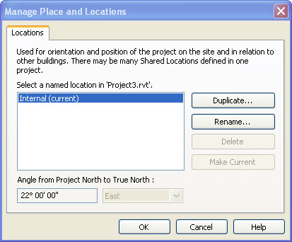
4. While in your site model goto Tools... Shared Coordinates... Publish Coordinates... and select your building(s) one at a time. This tool will share the coordinates of your site model (which is oriented correctly) with your imported building(s). Each building you select will require a named location. The default is Internal.
1. Once you have your building(s) modelled start a new project... Import your survey(dwg) into the new project and generate your toposurface from your imported instance.
2. Link your building(s) into your new site model and adjust their elevation and orientation so they are properly located in the topography. Do not relocate your topography. The topography is probably already oriented to true north and you'll want to preserve this orientation for rendering accurate sun angles.
3. Once your building(s) are located, place any building pads you need and make sure the elevations of your building(s) are where you want them. Now you're ready to share coordinates.
4. While in your site model goto Tools... Shared Coordinates... Publish Coordinates... and select your building(s) one at a time. This tool will share the coordinates of your site model (which is oriented correctly) with your imported building(s). Each building you select will require a named location. The default is Internal.
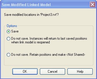
5. Save your site model. A dialog box will popup 'Save modified locations in 'Project.rvt' Go ahead and Save. You can also go to File... Manage Links... Revit... Save Locations. This procedure will open your linked model and save the new location into the linked project file but it won't affect any of your existing views in the building project file so not to worry.
6. Now that you have shared coordinates let's say you want the proper elevation to show in the levels of your building project file. While in your building project file just select a level... goto its properties... Edit/New... and change the Elevation Base parameter from Project to Shared.
7. We will often link the topography model back into the original building model for representing the topography accurately in sections and elevations. When you import the topography back into your building model make sure you Automatically Place... By Shared Coordinates. Your topography will import right where we want it to now that the two projects are sharing coordinates.
For more on Project Positioning see Steve Stafford's Revit OpEd.
Saturday, October 21, 2006
Instant Section Box
Scott Brown posted this on Zoogdesign ages ago but I thought it was pretty useful so I'll post it. While in plan view draw a floor plan callout... Go to any 3D view... Go to View... Orient... To Other View... and select your floor plan callout from the list of views. Rotate your view and you'll notice it's an instant section box. Very cool.
Friday, October 20, 2006
An ArchiCAD Blogger
Miguel Krippahl of Portugal is an ArchiCAD user and blogger who wants to know where are the ArchiCAD blogs are so if you find one or want to start one drop him a line.
Thursday, October 19, 2006
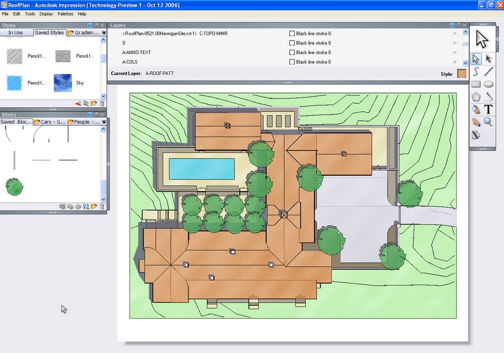
Autodesk Impression
Matt Rumbelow reports on his blog The Digital Architect that Autodesk Impression is now available for download. I've attached an image of one of our projects exported From Revit Building to dwg... imported into Impression... and rendered using out of the box tools. If you know photoshop, using this software is a snap.
Tuesday, October 17, 2006
A builder's perspective on BIM
Contractor's are starting to take a serious look at the BIM movement. If you're curious about what they're up to (bim) x is a new blog with a focus on BIM for contractors. Laura Handler is a Building Information Modeller with Tocci Building Corporation.
Friday, October 13, 2006
Building Pad Tips
A building pad will cut the topography down or raise topography up to the elevation you need for cut and fill. The building pad tool does not allow for sloping pads yet. Here are a few tips for managing building pads.
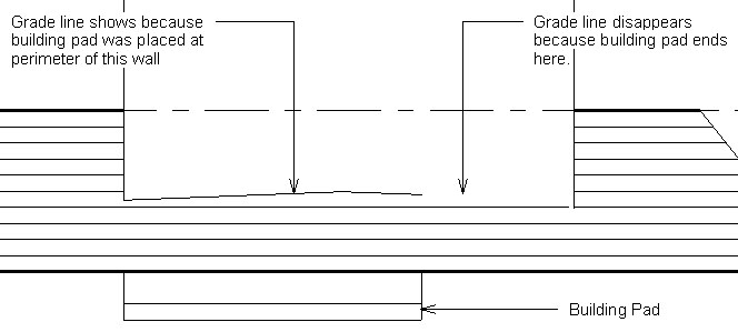
1. Let's say your grade slopes up to the building and you want to show (in your elevations) exactly where the grade meets the building. Well, Revit will not create this line for you and there is no way to join the geometry of a toposurface to a wall to get the grade line to show. So, you'll have to sketch a building pad along the perimeter of your building footprint to get the grade line at building footprint to show.
Hope these tips help you save hours of work trying to manage building pads.
Tuesday, October 10, 2006
Revit Performance
Because we do a lot of high-end residential design most of our projects are very detailed and put Revit's performance to the test. We've noticed performance hits when modeling large topography surfaces and turning on shadows in any view. So we asked Autodesk a few questions. I thought I'd pass the answers on to Revit beginners (to improve performance turn off shadows and topography when not needed).
Questions:
Does Revit take full advantage of 64bit processors?
Does Revit take full advantage of dual processors?
Does Revit take full advantage of high-end graphics cards?
Answers:
Revit Building does not take full advantage of 64 bit of dual processors yet.
Multithreading with dual processors is supported only by the Radiate process with the AccuRender engine within Revit. However, since Windows can take advantage of this technology, the overall performance perception is better with dual processors, since Windows can distribute multiple applications to separate processors. For example, one processor will control Revit and the other one Outlook, leading to overall better workstation performance. Autodesk is working closely with Microsoft in this important update, and you should expect full support for this technology in the future.
High end cards are supported as long as drivers for Windows are available, but there are not Revit-specific video card drivers. The only option within Revit is to enable hardware acceleration, which can me done in the Setting menu, under Options > Graphics.
Most performance issues can be resolved by following the usual recommendations for keeping the project file size small and switching the 3G RAM option on your operating system. Please follow the recommendation on these solution documents:
Enabling 3GB feature for Windows® XP SP2
http://usa.autodesk.com/getdoc/id=TS1057453
Reducing file size of Revit® projects
http://usa.autodesk.com/getdoc/id=TS1057977
Revit® and Virtual Memory
http://usa.autodesk.com/adsk/servlet/ps/item?siteID=123112&id=8018971&linkID=3770375
In related news, Wes Macaulay on AUGI reports that the Section Box tool is more responsive in Revit 9.1. If you aren't already a member on AUGI I highly recommend signing up.
Wednesday, October 04, 2006
Materials in Families
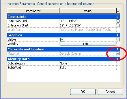
When building your families you might notice there are many ways to apply materials to your solids. Here are 4 ways to apply materials and some reasons for using each.
Element Properties
The most obvious method is to extrude a shape... go to its properties and specify a material for your solid form in the Material parameter under the Materials & Finishes group.
Element Properties
The most obvious method is to extrude a shape... go to its properties and specify a material for your solid form in the Material parameter under the Materials & Finishes group.

The Paint Tool
Goto Tools... Paint and you can also paint materials onto individual surfaces like the surface of a pool.
Goto Tools... Paint and you can also paint materials onto individual surfaces like the surface of a pool.
Material Parameters
While in the Family Editor go to Family Types... Add Parameter... and specify a new parameter of Type "Material." Now associate your new parameter to the Material parameter in Element Properties of the solid form (click tiny grey button). Once loaded into a project go to the Family's properties... Edit/New. You can now change the material from Family Type to Family Type. This method is very useful if you're expecting the material to change depending on the Family Type.

By Category
Extrude a shape... go to its properties and set your material to "By Category." You'll notice a parameter called Subcategory. To add a custom Subcategory go to Settings... Object Styles. After you've created your custom subcategory go back to the elements properties and assign the Subcategory to your solid form. Now when you load your family into a project file you can control materials globally in Settings... Object Styles. This method is very useful if you want to control the palette of your project globally from Object Styles.
Extrude a shape... go to its properties and set your material to "By Category." You'll notice a parameter called Subcategory. To add a custom Subcategory go to Settings... Object Styles. After you've created your custom subcategory go back to the elements properties and assign the Subcategory to your solid form. Now when you load your family into a project file you can control materials globally in Settings... Object Styles. This method is very useful if you want to control the palette of your project globally from Object Styles.

Friday, September 29, 2006
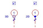
2D vs 3D Datum
You might notice that when you move the endpoint of a gridline in plan A it moves in plan B as well. Same goes for Reference Planes and Levels. Select a datum and it is selected in all views in which it is visible. You'll notice a blue icon that reads 3D. Click once on the icon and it switches to 2D mode. The datum is now view specific and free to move in this view independent from the same datum in other similar views.
 Applying a crop region or scope box to a view can also affect the location of your datum extents.
To set a datum to 2D mode in all views select the datum, change it's mode to 2D and click on the Propagate Extents button in the options bar. The datum choosen is now free to move independently in all similar views.

To set a datum to 2D mode in all views select the datum, change it's mode to 2D and click on the Propagate Extents button in the options bar. The datum choosen is now free to move independently in all similar views.
Embedded Walls
Walls can be embedded into other walls using the Cut Geometry command. Overlap two walls of different types... Select the Cut Geometery Tool... and click on the two walls (host wall first).
This behavior may be automatic for some curtain walls (like the storefront curtain wall). Go to the Type Properties of a Curtain Wall and you'll notice a parameter called Automatically Embed. This might be one way to model a niche.
Wednesday, September 27, 2006
Freedom Tower Webcast
For those of you interested in seeing how structural and mechanical engineers are collaborating in Revit to design the Freedom Tower there is a webcast Thursday, October 5, 2006 from 9:00 – 10:00 a.m. (PDT)
Surveys and Site Plans
We quite often import survey data into Revit from DWG files given to us by the surveyor. Here are a few tips to consider when importing (and exporting) surveys.
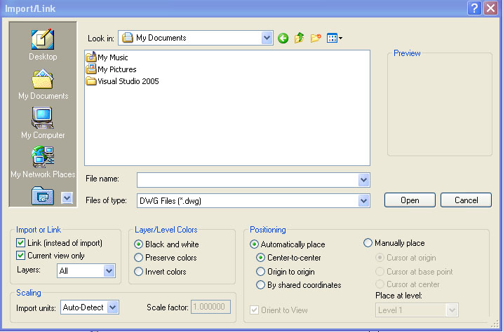
2. If you check "Current view only" your survey will only show in the active view (similar to detail lines). If you uncheck "Current view only" your survey will be visible in all of your views... elevations, sections, 3D views, etc (similar to model lines) and you'll have to adjust its visibility one view at a time.
3. Now let's say you've developed your site plan (with linked survey) and you want to export the data (including survey) back to DWG format. If you go to File... Manage Links... and Import your linked survey then it will export with the rest of your model to DWG format. If you don't Import your survey you'll notice that only revit components will export. The survey needs to be a part of the Revit model or Revit won't consider it when exporting your site plan to DWG.
UPDATE (09/27/06):
In Revit Building 9.1, when a DWG or DXF survey file is imported with the Current View Only checkbox checked, you cannot select the DWG/DXF instance to create a terrain model from the instance like you could with 9.0 and earlier versions. So imported data to be used for creating a toposurface must be imported with the Current View Only checkbox cleared. Thanks to Wes Macaulay on AUGI for posting this issue. Doesn't look like Autodesk is going to change this behavior.
Tuesday, September 26, 2006
Ductwork and Flues
Found an interesting feature in sweeps today. Create a sweep with an arched path. Go to the sweeps properties and you'll notice two parameters (Trajectory Segmentation & Maximum Segment Angle). Set the Trajectory Segmentation to true and choose a maximum segment angle. You now have yourself ducts and flues in Revit Building.
AU Connect now online
AU Connect is now online for those of you going to Autodesk University. Yes, I'm going this year. This will be my first year.

Monday, September 25, 2006
Modifying the Date Stamp
Sometimes users ask if the date stamp that appears on plots can be modified.
1. Select your titleblock... Edit Family... and you can change the font, size, visibility, and location of your date stamp.
2. What some beginners don't know is that you can also go to Regional and Language Options in Windows' Control Panel and customize the date and time formats.
3. If you still can't get the exact formating you want you can opt not to use the Date/Time Stamp parameter and create a new shared parameter of your own.
Friday, September 22, 2006
Loading Libraries
Goto File... Load from Library... Load Family and you'll notice icons on the left for Desktop, My Documents, My Computer, My Network Places, Imperial Library, Imperial Detail Library, and Training Files. Many beginners don't know that one can add to and customize this list of icons. Just goto Settings... Options... File Locations and add as many Libraries as you like.
To make loading families faster add a hotkey (like FF for Family Files) to the keyboardShortcuts.txt file:
"FF" menu:"File-Load from Library-Load Family"
NOTE: This tip can also be used for quickly loading project files. Go to File... Open and you'll see the same icons so you can add all your project directories too.
Wednesday, September 20, 2006
Family Templates
Let's say you have an office standard for how doors and windows should appear in plan view and you want to incorporate this or any other standard as part of your door and window templates. Here are a few things you should know:
1. Save your templates under a new name so users still have access to the door and window templates that ship with Revit.
2. To edit a template change it's file extention from .rft to .rfa.
3. Anything you place in the template can not be deleted once you open the template as a new family file (File... New... Family) so don't try to create new templates this way. Instead you should create new templates by changing an existing template file extention from .rft to .rfa and saving the template under a new name.
Monday, September 18, 2006
Two New Bloggers
Troy Gates of Costa Mesa is an Application Engineer for L.A. CAD with a new blog called Revit Coaster. I look forward to reading his future posts.
J B Zallan of Los Angeles is a Revit, Architectural Desktop, AutoCAD consultant and Autodesk Approved Instructor who's sharing his thoughts at CAD vs BIM... A junkies guide to overcoming addictions to lines.
Check out the new SpacePilot (and to think I was just joking with the guys at work the other day when I said that all Revit needs now is a joystick).
Tuesday, September 12, 2006
Head & Sill Height Behavior
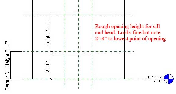
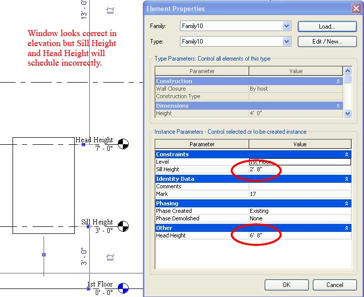
Did you model a rough opening height for your window that has say a sloping sill and now your head height is not accurate in your schedule? This is why.
We've recently discovered that the Head Height instance parameter in a door or window family is calculated from Sill Height + Height (easy right? wrong). It's not the Default Sill Height parameter as you would expect but rather the lowest point of your geometry that defines the Sill Height Revit uses to calculate Head Height (Head Height = 2'-8" + 4'-0" but should be 3'-0" + 4'-0") .
We've recently discovered that the Head Height instance parameter in a door or window family is calculated from Sill Height + Height (easy right? wrong). It's not the Default Sill Height parameter as you would expect but rather the lowest point of your geometry that defines the Sill Height Revit uses to calculate Head Height (Head Height = 2'-8" + 4'-0" but should be 3'-0" + 4'-0") .
Monday, September 11, 2006
Utility Lines Workaround
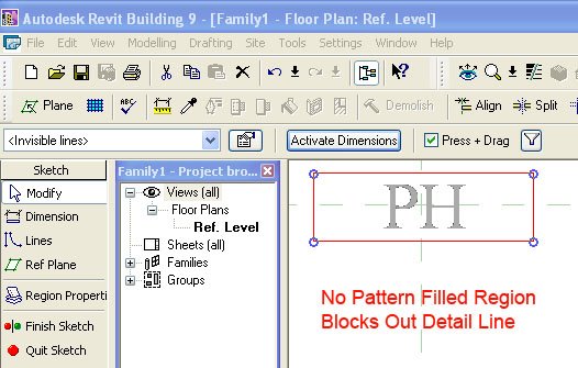
In AutoCAD you can add text to linetypes but you'll notice that in Revit you can't... unless you use this workaround. This workaround involves drawing a repeating detail line (with imported text) on top of a simple detail line.
1. Type out the text you want in AutoCAD (at a height of say 6") and save as a DWG.
2. Goto File... New... Family... Detail Component and import your DWG into your new Detail Component.
3. Place a masking region behind your imported text (as shown).
5. Goto Drafting... Repeating Detail... Properties... Edit/New... Duplicate... and give your repeating detail a name (phone line as an example). Set Detail Rotation to "90° Counterclockwise" and spacing to something like 10'.
6. Now draw a detail line in any view of your project. Draw your repeating detail over your new detail line as though tracing the detail line.

Combining repeating details and detail lines you now have a workaround for creating utility lines for gas, elec, phone, sewer, storm drain, etc. Daphne (one of our staff) suggested trying this.
Monday, August 28, 2006
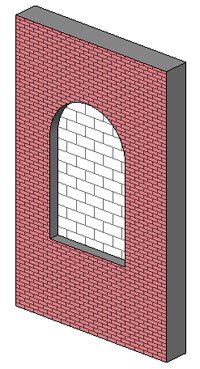
Wall Layer Wrapping Control
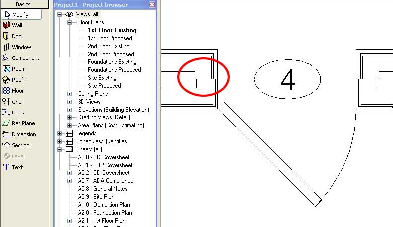
Let's say you've set your wall type parameter "Wrapping at Inserts" to Both because you want the exterior and interior finishes to wrap (as shown below).
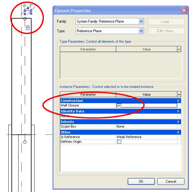
But you'll notice that by default Revit will wrap your layers to the centerline of the wall. I just discovered that you can adust where the wall wraps to. First thing you have to do is open the door (or other) family and add a reference plane (as shown below). Now select that reference plane and make sure that under its properties you change the Wall Closure parameter to TRUE. Lastly, add a dimension (like say 2 inches) and lock the dimension so that your reference plane is always 2 inches from your face of wall.
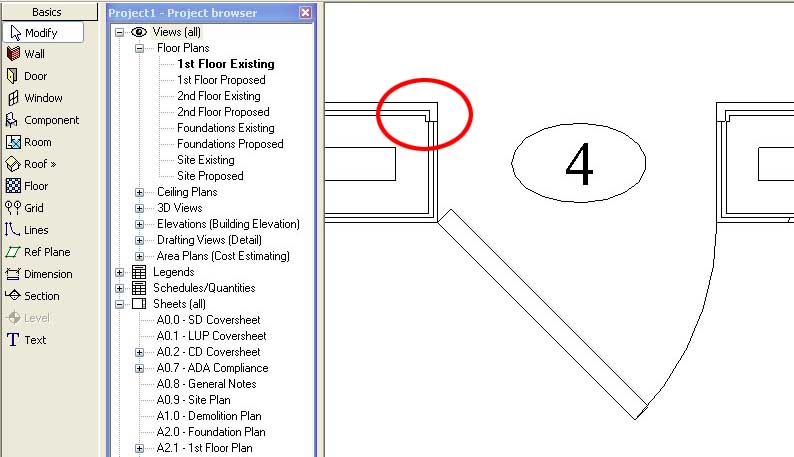
Now load your door family into a project and place it in a wall. Make sure the wall's Wrapping at Inserts parameter is set to Both. You'll notice that you can now control the location of wall layer wrapping.
You can also add a second reference plane to control exterior and interior wall layer wrapping separately.
But you'll notice that by default Revit will wrap your layers to the centerline of the wall. I just discovered that you can adust where the wall wraps to. First thing you have to do is open the door (or other) family and add a reference plane (as shown below). Now select that reference plane and make sure that under its properties you change the Wall Closure parameter to TRUE. Lastly, add a dimension (like say 2 inches) and lock the dimension so that your reference plane is always 2 inches from your face of wall.
Now load your door family into a project and place it in a wall. Make sure the wall's Wrapping at Inserts parameter is set to Both. You'll notice that you can now control the location of wall layer wrapping.
You can also add a second reference plane to control exterior and interior wall layer wrapping separately.
Wednesday, August 23, 2006
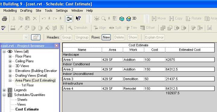
Cost Estimating
There are 3 ways we've found to estimate the cost of a project in Revit.
If you want to estimate the total cost of the project per square foot then setup an Area Plan scheme and Area schedule:
1. Goto Settings... Room and Area Settings... Area Schemes... New and add a scheme called Cost Estimating.
2. Goto View... New... Area Plan... Type... Cost Estimating... and break the project down into areas of differing cost per square foot.
3. To estimate the total cost goto View... New... Schedule/Quantities... Areas (Cost Estimating) and start adding the parameters you need to estimate the total cost.
4. You'll have to add a Calculated Value called "Estimated Cost" with a formula that looks something like (Area * Cost / 1 SF) so you can total the cost of each area.
If you want to estimate the total cost of the project by materials used then setup one of Revit's new Material Takeoff Schedules:
1. Some materials are estimated in Cost Per Linear Foot, some in Cost Per Square Foot, some in Cost Per Cubic Yard so I would first setup new project parameters for each estimate (Cost PLF & Cost PSF).
2. To calculate the total cost of materials goto View... New... Material Takeoff... Walls and start adding the parameters you need to calculate the cost of materials used in the walls.
3. You'll have to add a Calculated Value called "Estimated Area Cost" with a formula that looks something like (Area * Material: Cost PSF / 1 SF) so you can total the cost of material measured by area... (Length * Material: Cost PLF / 1') for "Estimated Linear Cost."
4. Now you can type in the cost for each material in the schedule. If you goto Setting... Materials... Identity you can also add a cost to each material here.
If you want to estimate the total cost of the project by unit cost then setup a Multi-Category Schedule:
1. To calculate the total cost of the project (by unit cost) goto View... New... Schedule/Quantities... Multi-Category and start adding the parameters you need to calculate the cost of all elements used. If you goto the Type Properties of each door, window, wall type, etc. you can also set a cost per unit here.
2. Now you can type in the cost for each material in the schedule.
3. Do not use Material Takeoff Schedule for estimating the total unit cost of doors and windows. Only use Material Takeoff Schedules when you want to schedule every material that is used in the door/window family separately.
If you want to estimate the total cost of the project per square foot then setup an Area Plan scheme and Area schedule:
1. Goto Settings... Room and Area Settings... Area Schemes... New and add a scheme called Cost Estimating.
2. Goto View... New... Area Plan... Type... Cost Estimating... and break the project down into areas of differing cost per square foot.
3. To estimate the total cost goto View... New... Schedule/Quantities... Areas (Cost Estimating) and start adding the parameters you need to estimate the total cost.
4. You'll have to add a Calculated Value called "Estimated Cost" with a formula that looks something like (Area * Cost / 1 SF) so you can total the cost of each area.
If you want to estimate the total cost of the project by materials used then setup one of Revit's new Material Takeoff Schedules:
1. Some materials are estimated in Cost Per Linear Foot, some in Cost Per Square Foot, some in Cost Per Cubic Yard so I would first setup new project parameters for each estimate (Cost PLF & Cost PSF).
2. To calculate the total cost of materials goto View... New... Material Takeoff... Walls and start adding the parameters you need to calculate the cost of materials used in the walls.
3. You'll have to add a Calculated Value called "Estimated Area Cost" with a formula that looks something like (Area * Material: Cost PSF / 1 SF) so you can total the cost of material measured by area... (Length * Material: Cost PLF / 1') for "Estimated Linear Cost."
4. Now you can type in the cost for each material in the schedule. If you goto Setting... Materials... Identity you can also add a cost to each material here.

If you want to estimate the total cost of the project by unit cost then setup a Multi-Category Schedule:
1. To calculate the total cost of the project (by unit cost) goto View... New... Schedule/Quantities... Multi-Category and start adding the parameters you need to calculate the cost of all elements used. If you goto the Type Properties of each door, window, wall type, etc. you can also set a cost per unit here.
2. Now you can type in the cost for each material in the schedule.
3. Do not use Material Takeoff Schedule for estimating the total unit cost of doors and windows. Only use Material Takeoff Schedules when you want to schedule every material that is used in the door/window family separately.

If you want to do cost estimating outside of Revit you might try exporting the Revit model as an ODBC and importing the database into Timberline. Haven't tried it yet myself.
Tuesday, August 22, 2006
The Revit Experiment III
Translating standard details from AutoCAD to Revit:
Now, you can import DWGs into Revit and not do anything else to them. You can also scan details and import them as images but we completely translated our details from PowerCADD to AutoCAD to Revit by way of DWG files so we could improve on their graphic quality once they were imported. Some things we noticed when importing DWGs:
1. Things that don't transfer well from AutoCAD to Revit include: text and leaders, dimensions, and hatch patterns. We typically remove dimensions, text, leaders and hatch patterns before we import DWGs into Revit.
2. We import (not link) the DWG into a Drafting View. If the "Link (instead of import)" option was checked when you imported the DWG you'll have to go to File... Manage Links... Import if you want to explode the dwg.
3. After importing a DWG we explode the detail. When you explode a DWG, Revit generates new (often unwanted) linestyles and names them according the the layer each object was originally assigned to. We typically reassign the imported linestyles to linestyles we created in Revit. We then add Revit's dimensions, text, leaders, and filled regions. When we are done we purge the unwanted linestyles that were imported from our DWG files when we exploded the DWG (File... Purge Unused).
4. Some might argue that you can PICK lines but we find exploding and reassigning linestyles much faster. By PICK lines I mean that you can place Revit Detail lines by essentially tracing over the imported DWG with the PICK lines tool.
5. After you get some experience translating a few details you should decide if re-creating a detail in Revit is faster than importing the DWG... might be for simpler details.
6. Non-ploting layers like Defpoints are not available in Revit.
7. If you save all of your roof details (as an example) into one project file you can later import these drafting views into any project you're working on. (from your project file just goto File... Insert from File... Views to import drafting views you've generated in other projects)
8. If you decide to import a DWG and you don't want to go through the trouble of translating it to a Revit detail consider setting up your DWG Import Settings to preserve lineweights (File... Import/Export Settings... Import Lineweights DWG/DXF).
Monday, August 21, 2006
The Revit Experiment II
Using Revit's 2D Drafting tools:
Because beginners are not completely familiar with all of Revit's tools and because they are often faced with a deadline, beginners will likely rely on detail lines and filled regions to piece together plans, sections, and elevations for their first few projects. This isn't necessarily a bad habit as long as they are using detail lines and not model lines (detail lines are view specific but model lines will show up everywhere). The Revit 3D model is just a place to start. Even advanced users use detail lines, filled regions, and detail components to refine their drawings. Revit will start your drawings but you have to finish them.
Downloading Revit content (family files) from the internet:
BIMWorld is developing BIMLibrary a centralized, standardized and universally accessible 3D CAD models database for the international AEC end user community. Read the article here.
We find that while we can download a lot of content from the internet we usually have to tweak (and sometimes completely rebuild) the family files to get them to coordinate with our in-house standards with the exception of content downloaded from some manufacturer websites which is what I think BIMWorld is driving toward.
You can see content they've already created:
www.revitcity.com
library.bimworld.com
Wednesday, August 16, 2006
The Revit Experiment I
7 months into my blogger experiment and I realize that I've talked a lot about Revit tips and tricks but I haven't really talked much about our transition to Revit. This will be the first in a series of posts on (drum roll).... The Revit Experiment.
In my first two years of using Revit I was using it almost exclusively for photo realistic rendering. I enjoyed setting up lighting and rendering mostly for interiors. The office I worked for didn't use Revit for developing working drawings but I do remember wishing that I could add text to linestyles (for phone, elec, gas, etc) and I remember having trouble understanding phases but I got a lot of help from users on Zoogdesign (now AUGI).
After two years I moved on to another office (a branch office with all of 4 staff) that was using MACs but was considering a move to PCs. So for a few months I learned how to use PowerCADD. The office eventually moved on to PCs and we used AutoCAD for a short time. When I mentioned that I had Revit experience the office bought a seat of Revit and I showed them what one could do with it, but I hadn't any experience doing working drawings in Revit... yet. In one year I've learned what I had to to develop working drawings, we've managed to build up some Revit content, we've organized our templates, and we are successfully developing our details and other drafting standards transfered from PowerCADD to AutoCAD to Revit. I will go into this in future posts. Now we are putting all of our projects into Revit.
I can't say it's been the smoothest ride. Transitioning from PowerCADD to AutoCAD to Revit on all the workstations meant resolving plotting problems every other day. This doesn't plot on the correct size sheet, that doesn't plot in the correct orientation, etc. Getting our plotter drivers properly configured has finally settled down, but I'm sure we'll have to grapple with this everytime we build a new PC.
Meeting once a week for an in-house Revit class has been very beneficial. Most beginners don't really know what questions to ask until they start using the software. Preparing content for a weekly in-house Revit class is a good idea but don't restrict yourself to any particular content. Users may already have questions prepared if they are truely interested in the software. Giving users room to try things, differently than you would, is also a good idea. Faced with a new program beginners sometimes find creative solutions to difficult problems. Supplimenting your in-house classes with classes offered by a reseller or Autodesk is highly recommended.
To be continued...
Tuesday, August 15, 2006
More Keyboard Shortcuts
1. Hold the Delete key and delete items one-by-one by clicking on them.
2. Hold the Ctrl key and drag an object to copy it to a new location.
3. Select an object and Alt+Enter to edit the Element properties.
4. When placing an object next to an angled line or wall the spacebar will align the object to the line or wall.
2. Hold the Ctrl key and drag an object to copy it to a new location.
3. Select an object and Alt+Enter to edit the Element properties.
4. When placing an object next to an angled line or wall the spacebar will align the object to the line or wall.
Friday, August 11, 2006
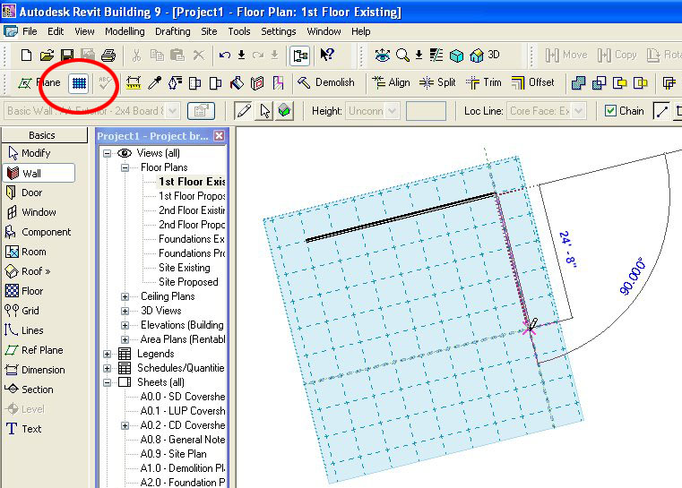
Revit's Drafting Machine
Overlooked by many beginners... For those of you who remember using drafting machines mounted to a drafting table you'll find a similar tool in Revit. Just turn on your Workplane (blue grid icon), set the spacing of its grid, and rotate the workplane to any angle you wish. Now any lines or walls that you draft will snap to the gridlines of your workplane. I recommend you use this feature if a wing of your building is not orthogonal.
Thursday, August 10, 2006
A few interesting features
1. Draw an arc (wall or line doesn't matter). Goto its properties and you can check "Center Mark Visible" if you need to dimension to the center point of an arc.
2. Callout a dimension and go to the dimensions properties... Edit/New... and play around with the Read Convention parameter. You'll notice you can now orient dimension text.
3. Shift + Nudge moves 10 times as far as Nudge.
4. Highlight Sheets (all) in your project browser. Now hold down Num Lock and press the Asterisk (*) key... or hold down Num Lock and press the minus (-) key. You'll notice the Sheets tree expands and collapses.
Monday, August 07, 2006
Autodesk University Blog
For those of you interested in following events at Autodesk University 2006 Joseph Wurcher's blog is devoted to a behind-the-scenes look at this year's conference.
Thursday, August 03, 2006
Press + Drag
Do you ever accidentally drag a wall or other model object across the screen when you didn't intend to move it? That's probably because the Press + Drag option is checked in your options bar.
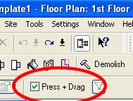
It might be nice if Revit would let you pick and choose which model and annotation objects can be moved with the Press + Drag option. I usually keep this checked for moving furniture, fixtures, and especially annotations but I do once in a while accidently drag walls or other model objects resulting in numberous warning messages.
Wednesday, August 02, 2006
Auto Dimension Options
Select the Dimension tool. In the options bar "Pick: Entire Walls" and select the "Options" button.
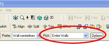
Select an exterior wall and you'll notice that you can now dimension the windows, doors, grids, and intersecting walls along the entire length of a wall.

Sunday, July 23, 2006
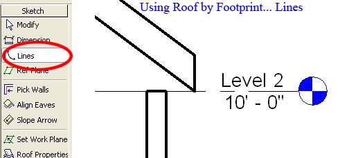
Rafters on Top Plate
If you've sketched your roof using Lines in the Roof By Footprint mode you'll notice that your roof may not be resting on your top plate the way you would expect it to.
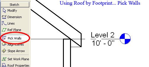
Instead of adjusting the elevation of your roof manually... sketch your roof using Pick Walls instead. The roof will now rest on your top plate (Level 2).
But by default Revit will treat your roof joists as trusses. To get your rafter resting precisely on your top plate you will have to go into the roof's properties and change the "Rafter or Truss" parameter to Rafter. This parameter will not be available if you've sketched your roof using Lines.
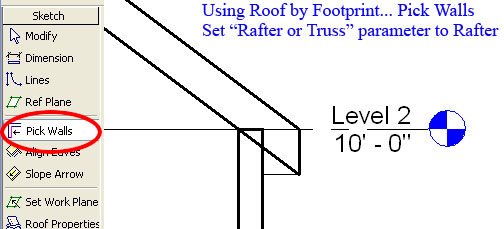
Understanding how Revit places a roof in section can be difficult if you're not aware of this Revit behavior.
UPDATE (12/05/06):
Don't mix pick lines and pick walls in the same roof sketch or you'll experience ill formed roofs.
Saturday, July 22, 2006
Stepped Foundation Plans
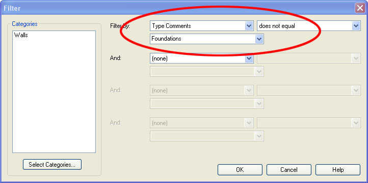
We often have split level projects and we've had a lot of trouble isolating the stem walls and footings from the rest of the model for use in a foundation plan... that is until Revit 9.0 came along. You can now use Revit Filters to isolate your foundation from the rest of your project.
1. Duplicate your Basic Wall: Foundation - 12" Concrete for each stem wall and footing size you need. You could use a Continuous Footing for your footings but we avoid Continuous Footings because their intersections don't clean up as nicely as Basic Walls.
2. Add the Type Comment "Foundations" for each of your new walls. Go to the wall's properties... Edit/New... Type Comments.
5. In Visibility/Graphics go to Model Categories and uncheck everything except Detail Items and Walls.
You can also use phases or worksets to isolate foundations, but we prefer the filter method.
1. Duplicate your Basic Wall: Foundation - 12" Concrete for each stem wall and footing size you need. You could use a Continuous Footing for your footings but we avoid Continuous Footings because their intersections don't clean up as nicely as Basic Walls.
2. Add the Type Comment "Foundations" for each of your new walls. Go to the wall's properties... Edit/New... Type Comments.

5. In Visibility/Graphics go to Model Categories and uncheck everything except Detail Items and Walls.

You can also use phases or worksets to isolate foundations, but we prefer the filter method.
Friday, July 21, 2006
Multiple Project Orientations
Lets say you have three buildings on your site and they are all at different angles. If you go to View Properties you'll notice that for orientation you only have a choice between Project North and True North, but what if you need to work in plan views that are orthagonal to each building?
Just setup duplicate floor plan views for each building and turn on your crop regions. Select the crop region and you can rotate the view to any angle you need. Because you've created duplicate views you can now preserve the different angles in each view for all time. Keep in mind, Revit will rotate your view in the opposite direction that you rotate your crop region.
Just setup duplicate floor plan views for each building and turn on your crop regions. Select the crop region and you can rotate the view to any angle you need. Because you've created duplicate views you can now preserve the different angles in each view for all time. Keep in mind, Revit will rotate your view in the opposite direction that you rotate your crop region.
Thursday, July 20, 2006
IFC/ODBC Software
I'm exploring Cost Estimating, Facilities Management, Specification Writers, and Material Takeoff softwares that utilize IFC and ODBC data that can be exported from Revit. I've added links to some of these softwares on my blog. Please feel free to comment if you have any experience using IFC or ODBC data exported from Revit.
Wednesday, July 19, 2006
Parametric Column Families
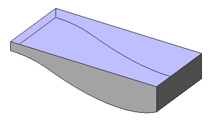
Have you tried everything and you can't get your column to stretch parametrically?
It can be a difficult task to figure out. There is no way to scale a column globally so that the proportions of your beautiful column are preserved (wishlist item alert) but we can show you how to build simpler columns that stretch properly.
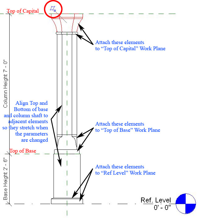
The example below is an adjustable column with adjustable base.
First thing you need to setup are reference planes. We have the given Ref Level and we've created a Top of Base and Top of Capital. Remember to goto the plane's properties and give each plane a unique name (we will use this later). Dimension these planes and attach your parameters (as shown below).
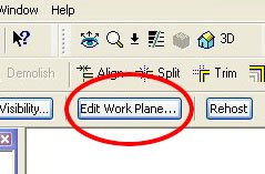
Second you have to create each of your elements for base and capital. Now the trick is that after you've created your elements you have to Edit the work plane of each element so that the elements are attached to the reference plane you would like them to "travel with." when adjusting the height parameters.
In this example we've attached our elements to Ref Level, Top of Base, and Top of Capital (as shown below).
It can be a difficult task to figure out. There is no way to scale a column globally so that the proportions of your beautiful column are preserved (wishlist item alert) but we can show you how to build simpler columns that stretch properly.
The example below is an adjustable column with adjustable base.
First thing you need to setup are reference planes. We have the given Ref Level and we've created a Top of Base and Top of Capital. Remember to goto the plane's properties and give each plane a unique name (we will use this later). Dimension these planes and attach your parameters (as shown below).
Second you have to create each of your elements for base and capital. Now the trick is that after you've created your elements you have to Edit the work plane of each element so that the elements are attached to the reference plane you would like them to "travel with." when adjusting the height parameters.
In this example we've attached our elements to Ref Level, Top of Base, and Top of Capital (as shown below).

Now load your column into a project and place it on the 1st and 2nd floors to make sure that the elements are correctly placed and stretch properly in both scenarios.
Tuesday, July 11, 2006
View Range & Visibility Lessons
We ran into two interesting View Range problems today.
Interior elevation tags from the first floor plan were mysteriously showing up on the second floor plan. That's because if the top of the crop region for an interior elevation view intersects the primary range (bottom clip plane) of the floor plan above, then the interior elevation symbol will show in the floor plan above. So you have to either lower the top of the interior elevation's crop region or you have to raise the bottom clip plane of the primary range in the floor plan above. Thanks to Steve Valenta on AUGI for pinpointing the exact solution.
While in the second floor plan we underlayed the 1st floor plan but the 1st floor plan walls were not visible while doors, windows, and fixtures were. That's because if the top of the wall below intersects the primary range (bottom clip plane) of the floor plan above, then Revit won't include the walls in the underlay. So we had to raise the bottom clip plane which shouldn't have been below the floor level anyway.
Monday, July 10, 2006
Free Revit User Guide
Three resources I've recently learned of:
1. If you bought a seat of Revit you should be able to get a 708 page Revit User Guide free of charge. Just type in your part number and serial number here. Posted by Damian on AUGI.
2. You can find resolutions to many common problems at Autodesk's Support Knowledge Base.
3. You can also send your wishlist directly to Autodesk here.
Monday, July 03, 2006
Cleaning wall intersections
Most wall intersections clean but we've had a few projects that put Revit's wall cleanup function to the test. To fix some intersections takes pushing and pulling. Here are a few tips:
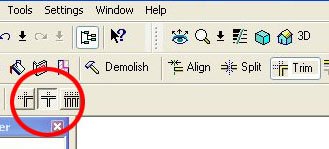
- Edit Wall Joins Tool. Sometimes all it takes is using the Edit Wall Joins Tool under Tools... Edit Wall Joins (it is also located on the toolbar above). Cycle through the various options to find one that cleans properly.

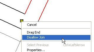
- Disallow Wall Join. Sometimes toggling the Disallow Join function will do the trick. Select one of the walls. You'll see a blue dot indicating the end point of the wall. Right click on this dot, do a "disallow join," then back to "allow join" and the intersection may heal.
- The "push/pull" method. If you have 3 or more walls intersecting you can try pulling them apart and reconnecting them in different orders. This pushing and pulling is about as much fun as dental work but it sometimes solves the problem.
- Nudging a wall can sometimes fix intersections at wall openings.
- Trim Tool. You can try pulling the walls apart and use "Trim/Extend Single Element." We've found this feature useful for cleaning up a lot of intersections that didn't clean up using the methods above. Try trimming walls in different orders until you find one that works.
- Split Tool. If nothing else works sometimes splitting one of the walls near the intersection will allow Revit to properly connect the wall intersection.
- Linework Tool. You can use the Linework Tool to clean up intersections but one of the above methods should do the trick.
- Cut & Paste Aligned. Autodesk's Knowledge Base also recommends you try cutting one of the walls (Ctrl+X) and goto Edit... Paste Aligned... Same Place.
- Edit Cut Profile. As a last resort you can use this tool to clean up connections.
- Join Geometry can also clean some connections.
Tuesday, June 27, 2006
Worksets Basics and Tips
I'll give you a basic intro to worksets and provide a few tips we've learned.
When you have a large project and you want multiple users editing a project at the same time you have to implement Worksets because Revit typically keeps all project data in a single project file unlike Autocad where we typically separate the project into multiple files.
Go to File... Worksets... to activate the Worksets feature in your project file. Revit will by default divide the project into 2 worksets "Shared Levels and Grids" and "Workset 1." All of your model objects will initially reside in Workset 1. You can further divide Workset 1 into other user-created worksets at some future time.
Save your new project file to a central server where everyone can access it. The file you're working in is now the Central File. Before making any more changes to the project file go to File... Save As... and save a local copy of this central file to your desktop (each user should save a local copy onto their desktop before they start working on a project file). You now have a Central File on the server and a duplicate Local file that you will be working in. If you ever wanted to make your Local copy a Central File goto Options when you Save As and check the box to "Make this the Central location after save."
Now from your local copy go to File... Worksets (there is also a worksets toolbar available). When a workset is opened it is loaded into memory and visible in all views. If you find the project is too slow with all the worksets opened then just close the worksets you won't be working on, but remember to open all the worksets again before plotting.
When you make a workset Editable you are the sole owner of a workset. You are the only person who can edit the workset.
When you select an object that's in a Non Editable workset you'll see a blue puzzle icon. Click on the icon and Revit will let you Borrow the element provided there are no users who Own the workset you're borrowing from.
You can rename and edit worksets that are User-Created. The three other workset types View Worksets, Family Worksets, and Project Standards are automated worksets that you can only turn on/off.
Here are a few tips we've learned in implimenting Worksets:
1. Enable worksets when you expect to have multiple users accessing the project file at the same time or when you expect the project is going to get so big that keeping the whole project open is going to be a strain on your workstations resources.
2. If you're going to open and close worksets for increased speed it is best to initiate the worksets feature as soon as possible. If you don’t initiate worksets early on you’re going to have to assign every model object to a workset after they’ve already been created and that can be a lot of unnecessary work.
3. If you are just going to use worksets so multiple users can access one file then the worksets feature can be enabled at any time. I would advise against adding more than the (2) default worksets unless the project file is just too slow and you're willing to spend half your time managing objects and the worksets they reside on.
4. When ever possible BORROW elements instead of OWNING worksets. We find that no matter how you divide your worksets users inevitably need to work on different parts of the same workset.
5. If you can help it do not use worksets to control visibility of objects in a view. Worksets are for closing large parts of the model when loading them is a strain on the resources of your workstation and for making project files accessible to multiple users.
There is a lot more to know about worksets but hopefully this gives you a place to start.
EDIT (4/18/2014): This post was, and continues to be, the most popular post on my blog so I thought I'd add a few additional tips.
6. If you have a site model with 10 buildings linked into it, consider putting each linked file on its own workset. When I'm working on a site model I always open "by selective worksets" to open just Workset 1, Shared Levels and Grids, and perhaps one of the buildings I'm modeling sitework around.
7. Keep in mind that when putting a linked model on a workset it has a setting for the workset in both instance and type parameters. Might be a good thing to know before you start.
8. There was a question about enabling worksets in a project template. Revit does not support worksets in template files BUT you can do all of your template work in a workshared project file (say if you've assigned multiple authors to one template), then make that project file a template file (detach and discard worksets) when you are ready to publish the template. More on AUGI
9. Never delete all the worksets (yes it has happened). You have to detach without preserving worksets and recreate a central with the "restored and default" worksets.
10. You can Own a workset with a special character username to lock everyone out of it (to prevent tip #9 for example).
11. Hint: If you are having performance issues consider that Local and central files are usually not the same size. Compacting one or the other or both are all options.
Tuesday, June 20, 2006
Section Annotation Features
There's more to Sections than meets the eye.
1. Goto the View... Section. You'll notice that you can select between a Building Section, Wall Section, and Detail View. Select the Detail View. In the options bar you'll notice that you can "Reference other view" (for referencing a drafting view that is already present). Place a Detail Section. Now goto View... Callout and place a Detail Callout. You'll notice that graphically they look different but they serve the same purpose and function in much the same way. Beginners often overlook that one has the choice between these two Detail Annotation styles.
2. Place a building section line and select it. You'll notice two blue circular arrows show up at either end of the section line. Click on it to cycle through section tail types. You'll also notice a blue breakline in the center of the section. Click on it to break the section into segments.
3. Place a building section line and select it. In the options bar you can "Split Segment." Place your cursor anywhere on the section line and start splitting the section line into segments.
4. Sometimes section lines disappear. Right click on the section and you can "Hide annotation in view." Goto the sections properties and you'll notice the parameter "Hide at scales coarser than." If your view is at a scale coarser than the parameter shown then the section annotation will disappear.
5. You can goto Settings... View tags... Section tags... to change the look of building, wall, and detail section annotations. Goto Settings.. View tags... Callout tags... to change the look of detail callouts. You can only choose from loaded Section and Callout Head annotation symbols. Edit those families for more custom heads.
Now a common problem is how do I get a section line EXACTLY where I want it?
Let's say you wanted a section at a very specific angle and at a very specific place in plan view that is not orthogonal. Just draw a reference plane at the angle you want (and in the location you want for your section line) then place your section line adjacent to the reference plane. The section line will snap to the angle of an adjacent reference plane but won't snap to the reference plane itself. Now, to align your section line with the reference plane the align tool isn't going to work. So, select the move tool, hover over the section tail (revit will snap to the section line), and just move the section from it's present location to the reference plane.
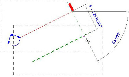
One last thing. If you don't like the look of Revit's Elevation tag you could design your own section head (for use as an elevation tag) and use these modified sections instead of the given elevation tags.
Monday, June 19, 2006
Callout Annotation Features
Goto View... Callout. You'll notice you can select a Floor Plan or Detail View callout. Select Detail View and draw a callout in plan view. Select the callout and goto its properties. You'll notice the parameter "Show in" is set to "Parent view only". Change it to "Intersecting views." Now place a building section in plan view that intersects the callout region.

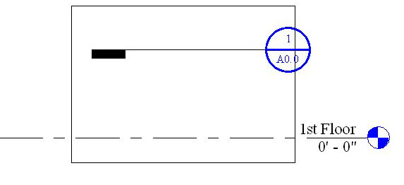
Tuesday, June 13, 2006
More Revit Content
Form Fonts is a new subscription service offering Revit content.
Revit Drop is another subscription service with some free content.
CadPlan has content if you don't mind that it's in metric.
SaleSoft has a content library also in metric.
Revit Drop is another subscription service with some free content.
CadPlan has content if you don't mind that it's in metric.
SaleSoft has a content library also in metric.
Friday, June 09, 2006
Sort by Submittal Package
Quite often we need to organize our plots for different submittal package sets (Schematic Design Presentation, Land Use Permit, Plan Check, Construction Admin, etc). Revit has the built-in ability to do this. Just goto File... Print... Selected views/sheets... Select... Here you can check off the sheets you want to plot and you can save those changes for different submittal packages. Unfortunately, there's not much you can do about any annotation references that cross over between submittal packages.
We decided that we also wanted to be able to sort the sheets in our project browser (and our drawing lists) by Submittal Package. It's possible but it's not an easy thing to do.
First, go to Settings... Project Parameters... Add. Now type in the Name "Submit for SD"... select the Yes/No Parameter... and check the category Drawing Sheets.
Now goto Settings... Browser Organization... Sheets... New. Call your new Browser Tree "Submit for SD". Goto the Filter tab... Filter by Submit for SD... Equal To... Yes. Now exit the Browser Organizer (while saving changes), right click on Sheets (all) in your project browser, and click on Properties. You'll notice your new Browser Tree "Submit for SD" is in the Type drop down list. Select the "Submit for SD" option.
Now goto View... New.. Drawing List... and add ALL the parameters (including Submit for SD). Leave the name Drawing List. If you look at your new schedule you'll notice that under the column Submit for SD you can check which sheets you want to apply to your Schematic Design Submittal Package. If the check boxes are greyed out just select them one at a time to active them. You might also notice that as you check and uncheck different sheets that your list of sheets in the project browser changes too.

Now that we can sort our project browser by Submittal Package we have a new problem. The Drawing List on our coversheet shows ALL the drawings from ALL the different packages. We're going to need a different Drawing List for each submittal package. You'll probably want different Coversheets for each submittal package too so set up a coversheet for each of your submittal packages starting with an SD coversheet.
Goto View... New.. Drawing List... and add the parameters: Submit for SD, Sheet Number, and Sheet Name. Click on the Formatting tab and select Submit for SD. Make this parameter a Hidden Field. Click on the Filter Tab and Filter by Submit for SD... equals... YES. Select OK and rename this drawing list "Drawing List - SD". Now you can do the same for each of your submittal packages (LUP for Land Use Permit, ConDocs for construction documents, etc). Drag each of your new Drawing Lists into their respective coversheets.
Now if Autodesk would add the Print Set parameter to Drawing Lists fields then we could coordinate the sheet browser, drawing list, AND the Print Range settings.
Wednesday, June 07, 2006
Edit Cut Profile Tool
Do you want a niche cut out of your wall for a soap dish or other amenity?
Draw a wall in plan view. Goto Tools... Edit Cut Profile. Select the wall in plan view. Now sketch a shape for your cut (like you would the Split Face Tool) Finish sketch and you'll notice the shape of the wall was cut. While in edit mode a blue arrow controls which side you want to keep.
This tool works in Plan, Section, and RCP views. This tool is view specific (ie. Any niche you cut out of your wall using this tool won't show in any other view.)
Thursday, June 01, 2006
Split Walls with Gap
Brian Tuffin wrote an interesting blog post on Modifying the Split Command. By editing the Revit.ini file one can add the tool "Split Walls with Gap."
This tip was also posted by Chad Smith on AUGI.
This tip was also posted by Chad Smith on AUGI.
Wednesday, May 31, 2006
Rooms in a split level environment
Are your room tags not working? Maybe the new room tool could use a little explaining. It sure needed explaining to me.
1. The cut plane (orange) of your floor plan view range must cut through ALL the rooms you want to tag in that view. Setting the proper cut plane height is especially critical if you have a split level project.
1. The cut plane (orange) of your floor plan view range must cut through ALL the rooms you want to tag in that view. Setting the proper cut plane height is especially critical if you have a split level project.

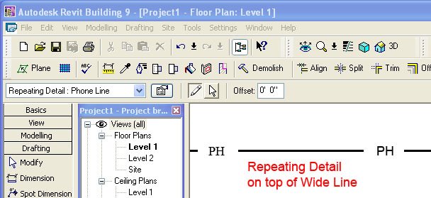
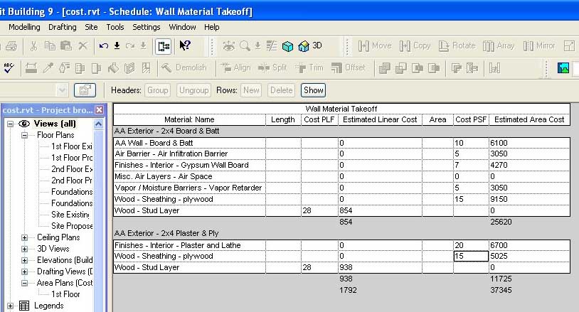
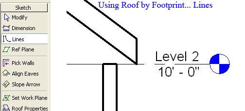
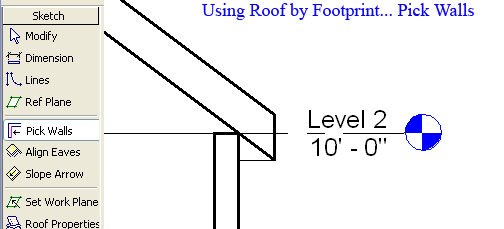
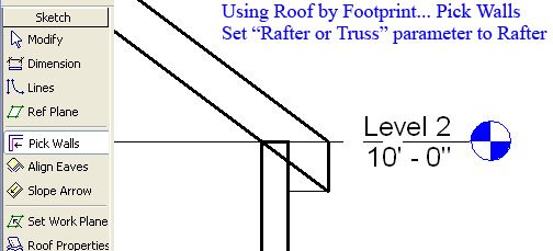
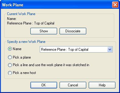
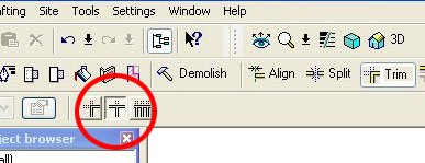
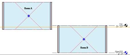
2. If your cut plane is below the lower limit of a room, tags in that room may only display a ? instead of the room name. If this happens then you'll have to raise your cut plane so that it intersects the room, delete the old room tag, and replace the room tag.
3. If your cut plane is above the upper limit of a room you simply won't be able to tag the room.
4. Once you have your cut plane at a height that intersects the rooms you want to tag THEN you place your plan regions where the cut plane is not properly intersecting windows and doors.
5. Rooms will ignore the cut plane of plan regions.
Tuesday, May 30, 2006
Anchor vs. Pin Position
Two tools some beginners aren't aware of are the Anchor Symbol and Pin Position Tools.
Draw three walls, in plan view, parallel to eachother. Dimension the distances between each wall with one dimension string. And set the two lengths EQ. Now delete the dimension. You'll get the warning message "A Dimension with Lock and/or EQ Constraints is being deleted." Select OK to keep the walls constrained.
You'll notice now that when you select one of the walls a blue anchor symbol shows. If you decide to move the selected wall this symbol tells you which of the three walls will remain anchored while the other two constrained walls stretch equadistant to eachother. You can select which wall will be anchored by dragging the anchor symbol to one of the other walls.
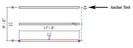
Now lets say you decide you want to use the Pin Position tool (a pin icon located in the toolbar). Once pinned a wall will not move regardless of which wall has the anchor symbol. The pin position tool overrides the anchor tool.
Thursday, May 25, 2006
Family Specifications Manual?
Robert of Philadelphia, PA works for an office that has written an in house specification for family creation. Very interesting read.
Revit Standardization: Family Specs
Revit Standardization: Family Specs
Wednesday, May 24, 2006
Electrical Symbols
We have a very large residence that requires an overall coordination plan at 1/8" scale and 5 individual quadrants at 1/4" scale because a complete 1/4" scale plan isn't going to fit on a 30x42 sheet.
Well after placing the electrical outlets that come with Revit we noticed that in plan view the outlet symbol doesn't scale when you change the floor plan scale from 1/4" to 1/8". In other words the symbols appear much larger relative to the floor plan when viewed at 1/8" scale. The reason is because the plan view symbol nested in Revit's electrical outlets are Generic Annotations and by design Generic Annotations don't scale when you change a view's scale. Well we wanted the symbols to scale with the floor plan so they wouldn't overwhelm the drawing at 1/8" scale so we drew our outlet symbols as Generic Models instead. Generic Models will scale with the rest of the floor plan.
Now that we've got our outlets and switches scaling the way we like we have a new problem. The text for our Switches (Dimmer, Door-op, Four-way, etc) doesn't show anymore. That's because when we were using nested Generic Annotations, text was supported. Now that we are using nested Generic Models for our electrical symbols text isn't supported. The solution is to create your text in Autocad, import the dwg into your Generic Model, import your Generic Model into your Electrical Family, and there you have it.
Monday, May 22, 2006
A New Blogger
Green Revit is a new blog, with a focus on the correlation between Revit and green building design.
Friday, May 19, 2006
Another Revit Wishlist
A lot of people post wishlists on their blogs. Here's my contribution:
- Speed... Revit can be too slow for many users.
- Wall intersections still need a little improving when phases are applied. Right now when a demo'd wall, new wall, and existing wall intersect at a "T" junction the intersection doesn't clean up in all phases.
- Building Pads are not phase aware but should be
- Schedules should be able to reference window sill/head/jamb details. Right now we have to manually input the detail number and sheet number into our schedules.
- Add a scale factor for families. We have columns that we would like to scale while keeping the proportions of all the shapes constant. A global scale factor parameter would do the trick.
- Add Variable Transparency option to Filled Regions
- Add system families, annotations, titleblocks, and detail component families to Multi-Category Schedules so we can manage loaded families utilizing schedules. AND ability to add Project Parameters to titleblocks and annotations for same purpose.
- A Family manager for changing subcategory names, flagging families for correction, etc.
- A divide tool for splitting walls and lines into equal parts
- A stretch tool similar to AutoCAD
- Improved spline tools for trimming, filleting, and splitting splines. Right now moving the endpoint of a spline moves all the points and you can't trim, fillet, or split splines.
- When demolishing a door, the infill wall Revit automatically places should be optional.
- Generic Model Opening and Void edges don’t show when phases are applied.
- Elevations should split/jog similar to the Section Tool.
- Irregularly shaped Crop Regions should be supported like the vpclip tool in AutoCAD.
- Crop regions that plot at varying thickness for cropping interior elevations.
- A pop up message at the other user's computer when you put in a request for worksets.
- Expanded Filter Selection Tool: adding ability to sort annotation and model objects by level, phase and worksets.
- Add Text subcategories for turning selective text on and off.
- Separate interior and building elevation tags so one can selectively turn off one OR the other in Visibility/Graphics... Annotation Categories.
- Tools for illustrating and calculating egress
- Submittal Package Utilities. Ability to sort sheets, drawing list, and print range by type of submittal package. A host of submittal package sorting and documenting tools would be of great benefit. When we submit a package to a client, contractor, consultant, or agency it would be of great benefit if we could just go to one place and check off the drawings that we want to plot, record for future reference, list on our coversheets, and display in our sheet browser.
- When walls of different types meet Revit should cleanup the connection in elevation.
- Key Plans tool needed (we have a large floor plan that is divided between sheets)
- Separate interior and building elevation tags in Visibility/Graphics.
- Separate Detail and Model Lines in Visibility/Graphics.
Monday, May 15, 2006
Coarse, Medium, and Fine - Wall Patterns
You might notice that wall patterns disappear when you're switching between Coarse, Medium, and Fine detail levels.
Let's say you want to show your view (plan/section) in Coarse detail level:
To edit the pattern select the wall...
go to the wall's properties... and Edit/New...
Here you can change the Coarse Scale Fill Pattern parameter.
Now let's say you've switch your view to Medium or Fine detail level:
To edit the pattern select the wall...
go to the wall's properties... and Edit/New...
edit the structure...
and select your new material...
Here you can select your new cut pattern from available fill patterns.
I'm not sure why parameters for Revit's coarse, medium, and fine detail levels cut pattern settings are separated but this is a common question so I thought I'd post the answer.
Friday, May 12, 2006
Google's 3D Warehouse
You can now get 3D content from Google in the form of SketchUp files. Revit 9 supports the importing of SketchUp files. There's not a lot of content yet but I'll be watching this.
Google's 3D Warehouse
Google's 3D Warehouse
Monday, May 01, 2006
Upgrading Families
Our family library has grown considerably and we were tired of seeing "THIS IS A ONE TIME UPGRADE PROCESS ONLY" every time we opened a family file that was saved in Revit 8.1.
Well, Autodesk has a Family Upgrade Utility for upgrading all of your old family files to the new version. Make sure you backup your library before trying this. This also doesn't work over a network so you'll have to copy your library to your local harddisk before executing the procedure.
Well, Autodesk has a Family Upgrade Utility for upgrading all of your old family files to the new version. Make sure you backup your library before trying this. This also doesn't work over a network so you'll have to copy your library to your local harddisk before executing the procedure.
Monday, April 17, 2006
Repeating Detail Tool
Do you want to add tile pavers on a slab, 2x6 joists in a section drawing, or wood shake to a roof section? The repeating Detail Tool will draft detail components along a line you define at spacing you define. Go to Drafting... Repeating Detail... Edit/New... Duplicate. Here you can add new Repeating Details to your project. You must first load the detail component you want to repeat.
Any Revit Text you place in a Detail Component will not show up when you go to use the component in a repeating detail. If you want to add text to your repeating detail you'll have to first import AutoCAD text into your detail component.
Any Revit Text you place in a Detail Component will not show up when you go to use the component in a repeating detail. If you want to add text to your repeating detail you'll have to first import AutoCAD text into your detail component.
Thursday, April 13, 2006
Beginner Bloopers
Nested Families: We've had window families that were getting to be upwards of 2 MBs making the project file huge (over 140MB). On average window and door families should be 140kb - 400kb (we do have a few ornate doors that are larger) . It turns out one of our users was loading window families into window families into window families. Make sure you purge unused when you're done with your family.
Levels: You shouldn't have to add a lot of levels when they are only inches apart. Too many levels clutter elevations and sections so keep an eye on how your users utilize levels. Make sure your users know that they can OFFSET heights of objects. Levels can be difficult to modify later once they've been established.
Paint Tool: The Paint tool (PT) is for applying materials and patterns to a model surface. You can not import a dwg file (or draw a boundary using detail lines) and expect the paint tool to fill the area within the drawn boundary. The Paint tool is not like photoshop's Paint Bucket Tool.
Sitework - Roads: When I was learning how to build sitework I was using the Split Surface tool to create roads and walkways. It didn't occur to me at the time to create subregions instead. Use subregions to distinguish asphalt roads and walkways from topography. Creating roads and walkways with the split surface tool is a bad idea. Once you split a surface, editing the boundary of that split surface becomes very difficult and often results in "can not triangulate surface" error messages.
Saturday, April 01, 2006
Door & Window Tips
There is a lot one can learn about the family editor. I'll just briefly describe what it is and what tips will help you get started with creating custom doors and windows.
The family editor is where one models complex geometries such as door families, window families, furniture families, custom annotations, fireplaces, etc. The tools available in the family editor are somewhat different than those available in a project file. In a family you can place detail components, symbols, and model lines just as you would in a project file, but you can also place nested families, symbolic lines, and parametric parameters. A nested family is simply a family loaded into another family. If you're in the habit of loading nested families be sure and purge unused nested families before you load a family into your project file (to keep the file size down).
There are two ways to work in the family editor. Create a family file that is separate from the project file (go to File... New... Family) or build an in-place family (go to Modelling... Create). We only use in-place families for some sitework and some building details. Mostly we generate family files. Family files (.rfa) can be saved for use in other projects. Building a library of family files will save you time on future projects.
If you're going to build a door, window, or other family you'll probably want to start with one of the templates Revit offers (go to File... New... Family and choose the appropriate template). These are a few tips I'd recommend:
1. The first place I always go to after starting a door or window family is the Family Type. Here you can change parameters for width and height which are already setup for you. One family file could have many types. A type is defined by its parameter values. If you want one family type to be 3' x 3' and the other to be 3' x 4' then you'll want to create NEW family types and name them according to the parameters that change (size in this case).
2. In a door or window family template select the reference plane that is centered in the family and go to it's properties. You'll notice that the parameter "Is Reference" is called out as "Center (Left/Right)". This is the reference plane that Revit uses when you're dimensioning to the centerline of your doors and windows in plan. Always try to keep this reference plane centered in your family or you'll have problems further down the road when you want to dimension to centerline of door or window. Checking for this is something beginners often overlook to do.
3. In plan view you'll notice that the Exterior and Interior are marked. Always keep in mind which side is which when you're building your window or door. You'll also notice a Flip Control (two blue arrows). Don't delete this annotation as you may want to flip the door or window direction after placing it in your project.
4. If you want your door or window to stretch properly when you change it's width or height in the Family Types first setup reference planes that define the basic geometry of your door or window and dimension them (with parameters if you want them to stretch). Then you should dimension or align your solid shapes to the established reference planes or lines so that the modelled shapes will stretch with the planes. I would recommend you take a look at "Casement 2x3 with Trim.rfa" in the Imperial Library as an example of a window that stretches properly.
5. Always check to see that your family stretches properly in x, y AND z axis. One thing you can do to make sure your door or window will work in walls of differing thicknesses is to select the wall in your family template and change its structure from 6" to maybe 10" (go to the walls Properties... Edit/New... Structure). Checking this behavior is something beginners often overlook to do.
6. If you want the correct width, height, and sill height to show up in the door and window schedules I recommend you dimension these basic parameters in your doors and windows. What happens too often is when a user is in a hurry to make a door or window he/she ignores dimensioning these parameters and the schedule will read whatever width and height are established in Family Types (whether they are right or not). You'll end up with the wrong height and width in your schedule if you don't at least dimension these basic parameters. To assign a parameter to a dimension simply select the dimension and change its Label from "None" to the desired parameter.
For more on families see Working with Autodesk Revit Components
Wednesday, March 29, 2006
Key Plans
Revit does not currently have a Key Plan Tool so this is what we do when we need a Key Plan on our sheets.
1. Export your Base Plan to DWG (just the unit boundaries)
2. Create a Detail Component. File... New... Family... Detail Component.rft
3. Import your Base Plan. File... Import... DWG
4. Add a Yes/No Parameter for each unit or quadrant. Family Types... Add Parameters... Type Yes/No... Set Instance Parameter... give each unit or quadrant a name.
5. Draw Filled regions for each unit or quadrant of your Base Plan and assign each one a Yes/No Parameter. To do this go to the Filled Region's properties and you'll find a Visibility check box. At the far right there is a tiny grey box. Click on it and select your new Yes/No Parameter as the parameter that defines the visiblity. Do this for each filled region.
6. Now load your new Detail Component into a Legend View in your project and set the appropriate scale.
You can now turn on and off each quadrant using the Yes/No Parameters you set up in the element's properties.
Tuesday, March 28, 2006
Model, Symbolic, Detail and Reference Lines
Which one do I use?
Well, when you're in the family editor you can draw symbolic lines, model lines or reference lines.
1. Symbolic lines only show in plan, elevation, or section depending on which view you're in when you draw them. Symbolic lines are typically used to "represent" door and window swings in plan and elevation.
2. Model lines will show in ALL views because they are part of the model. It's not very well documented but (while in the family editor) Detail Components placed perpendicular to a model line will "sweep" along the model line drawn (Search Augi Forums for Ultra Lightweight 3D Models to see an example). We also use model lines as a quick way to "represent detail" in some families.
3. Reference lines are essentially four intersecting reference planes. They can be used when you want to add a door swing angle parameter to your doors. Reference lines and planes should ALWAYS be used when using dimensioned parameters in a family. For more on reference lines and planes read Steve Stafford's Once Upon a Reference Plane.
When you're in the project you can draw detail lines or model lines.
1. Detail lines, like detail components, are view specific or part of the view. Anything you "draft" in a view will not show up in other views unless you copy and paste the elements into other views.
2. Model lines drawn in a project file are like those drawn in the family editor. They will show up in all views because they are part of the model.
To turn model lines into detail lines... select all model lines cut and paste into a filled region sketch. To turn detail lines into model lines... select all detail lines cut and paste into a floor sketch.
Monday, March 27, 2006
View Range
The use of View Range can be a difficult concept to grasp. The image below has been circulated around and explains how CUT, PROJECTION, and BEYOND linestyles are used by the View Range tool found in View Properties (VP) and Plan Region Properties.
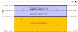
CUT and PROJECTION linestyles are controlled globally in Settings... Object Styles and for each view in Visibility/Graphic Overrides (VG). BEYOND linestyle is controlled globally in Settings... Line Styles and for each view in Visibility/Graphic Overrides (VG).
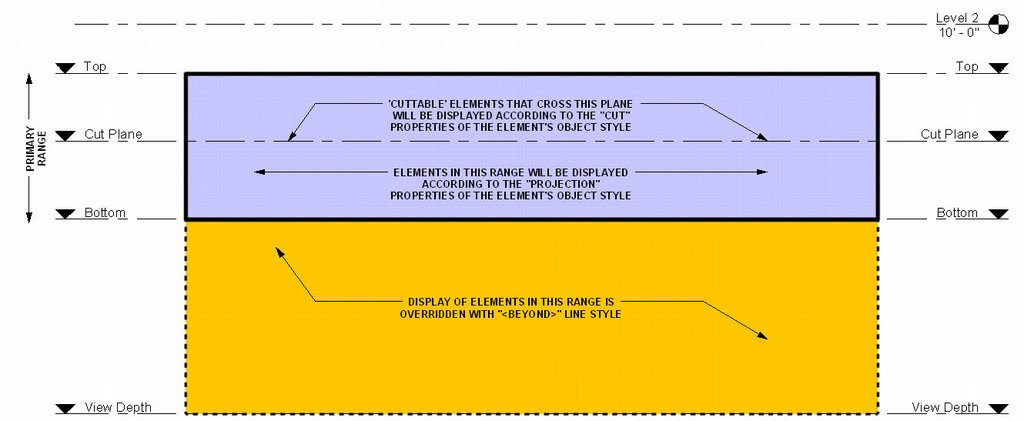
CUT and PROJECTION linestyles are controlled globally in Settings... Object Styles and for each view in Visibility/Graphic Overrides (VG). BEYOND linestyle is controlled globally in Settings... Line Styles and for each view in Visibility/Graphic Overrides (VG).
Tuesday, March 21, 2006
Floor Plan Backgrounds
Let's say you're doing your own mechanical, electrical, structural or other drawings that require a floor plan that is greyed or halftone (a background). We've found two ways to accomplish this:
Display Model As Underlay: The easiest way is to Duplicate your Proposed Floor Plan view (without Detailing) This is done by right clicking on your floor plan view in the project browser and selecting Duplicate. Now go to the View's Properties and you'll notice a Display Model parameter. By default this is set to Normal. Switch this to As Underlay. Now you can add your view specific tags, annotations, symbols, detail lines, etc. on top of the model. Unfortunately your lighting, furniture, electrical and other families will also be greyed out. If you need to show some model elements Normal then it's on to the next approach.
Visibility/Graphics Halftone: Duplicate your Proposed Floor Plan view (without Detailing) This is done by right clicking on your floor plan view in the project browser and selecting Duplicate. Now go to the view's Visibility/Graphic Overrides (VG). Under Model Categories select ALL. Now unhighlight Electrical Fixtures and Lighting Fixtures and check the Halftone box for one of the highlighted categories. Notice all the highlighted categories are now set to halftone. Click OK. You now have a floor plan background for your lighting and electrical work. Do the same for Detail Items, Electrical Equipment, Plumbing Fixtures, Furniture, Structural Framing, etc. for other disciplines. Go to View... Save as View Template... and you can save these changes to a View template for use in all your projects. To further configure View Templates go to Settings... View Templates.
To transfer View Templates and other standards from your project to a template file see Jay Polding's Importing Wall Styles.
Thursday, March 16, 2006
Revit's 16 lineweights
Revit has 16 lineweights. They say that the lineweights should be constant no matter what scale your drawing is at. We've found that's not always true. Go to Settings... Lineweights... and you'll notice that Revit has lineweights setup for 6 View scales from 1" = 1'-0" to 1/32" = 1'-0". Well what happens if you have a drawing at 1:50? Revit uses the closest thing (1/32" in this case). The good news is that you can ADD scales that Revit doesn't have setup. The bad news is you'll have to plot the 16 lineweights after you've setup your new scale and compare them with the default scales to get the settings right.
Maybe in a future release Autodesk will setup their default.rte file with the appropriate lineweights for all default scales.
Maybe in a future release Autodesk will setup their default.rte file with the appropriate lineweights for all default scales.
Wednesday, March 15, 2006
Shared Parameters
Did you add a parameter to a family but when you loaded the family into your project the new parameter won’t schedule or show up in your tags? You have to make it a Shared Parameter.
Creating the Shared Parameter File:
1. While in Revit (doesn't matter if you're in a family or project file) go to File... Shared Parameters... Create... give the txt file a name. This shared parameter file can be used on all your office's projects if you wish. Now Create Group... and add parameters you want to see in schedules or tags. The Shared Parameter file is now loaded into your Revit session for use in other family or project files.
Adding the shared parameter to your family and project files:
1. While in your family editor go to Family Types... Add Parameter... Shared Parameter... and Select your new parameter. Now while in your project file go to the schedule you want the parameter to show up in and go to View Properties... Fields... Add Parameter... Shared Parameter... and Select your new parameter.
2. If you're adding a parameter to your tags... While in your project file go to Settings... Project Parameters... Add... Shared Parameter... and Select your new parameter. Don't forget to check which family category to apply the Shared Parameter to.
If you exit all your Revit files but leave Revit running you will see that under File... Shared Parameters your shared parameters file is still loaded for use in other family or project files.
For more on Shared Parameters search Steve Stafford's RevitOpEd.
Friday, March 10, 2006
Family Visibility Control
When creating a door or other family we find that when loaded into a project we sometimes like to be able to switch on and off parts of the family but not the whole family. We have found three ways to accomplish this.
Visibility: We like to use symbolic lines to represent doors and windows in plan so we like to turn off the visibility of our model objects (glass and panel) in plan view. While in your family editor, this is simply done by selecting the object you want to hide and clicking on the Visibility button in your tool bar above. Note that this method is for turning off objects that you NEVER want to see in plan, section, elevation, or at specific Detail Levels.
Object Styles Subcategory: Another way to control the visibility of parts of a family is to setup new subcategories. While in your family editor goto Settings... Object Styles. From here you can add subcategories. Now select an object in your family and goto its properties. You'll notice that you can change the object's Subcategory. Load your new family into a project. You can now control the visibility of parts of your family GLOBALLY under Settings... Object Styles or in a SPECIFIC VIEW under View... Visibility/Graphics.
The Yes/No Parameter: While in the family editor goto Family Types... Add Parameter... And create a new Type parameter with Type (Yes/No). Now finish the Family Type and select any object in your family. Goto it's properties and you'll find a Visibility check box. At the far right there is a tiny grey box. Click on it and select your new Yes/No Parameter as the parameter that defines the visiblity. Now exit the element properties and go back into the Family Types. From here you can control the visibility of the object. Just add two new family types and uncheck the new parameter in one type while leaving it checked in the other type. The object will appear grey while in the family editor, but once you load the family into a project you will find that you can now switch on or off part of the family by switching between family types.
Wednesday, March 08, 2006
Naming Conventions
If you're responsible for establishing a naming convention for your Project Files you're probably wondering what other offices do. This is what we've established.
Project files: [project number] [project name] - [Central or User] - [version]
Example: 0513.00 Johnson - Central - 03.rvt
Family files: [office initials] [family category] - [title] - [version] - [project precedent]
Example: AA Window - Dbl4x4 - 01 - Garden Lane.rfa
Group files: [office initials] [group category] - [title] - [version] - [project precedent]
Example: AA Door - Dutch Door - 02 - Hope.rvg
1. We name our files from general to specific so that when they sort in windows explorer finding what you want is easier.
2. Office Initials are reserved for files that are established standards. If it doesn't have our initials it isn't a standard yet.
3. Version numbers are necessary because we often have many versions of the same thing.
Tuesday, March 07, 2006
Dimension Text Override
To override or not to override... Which camp are you in?
Maybe you've noticed that you cannot override dimension text like you would in AutoCAD. You can however add a Prefix and Suffix to dimensions under the dimension's Properties. If you absolutely must override dimension text (for Verify In Field or other common notes) here is what we've done:
1. Select the dimensions tool and goto its properties.
2. Click on Edit/New.
3. Click on Duplicate to create a new Dimension Type.
4. Give the dimension type a new name like... Blank
5. Now Change the text size to 1/256" (smallest you can get)
6. Change Units Format to Decimal Feet and rounding to 0 decimal places. You now have a font that is so small it won't register.
7. Now just use the Text tool to add whatever text you need on top of your "blank" dimension.
Subscribe to:
Posts (Atom)